Raypak 302B-902B User Manual
Page 24
24
Installer action is required to electrically enable your
heater to operate after making the power connections.
You must make a closed contact connection on Stage
1 connector of the Central Point Wiring (CPW) board
for temperature control connections. This will be done
based on the controller option selected with your
heater order.
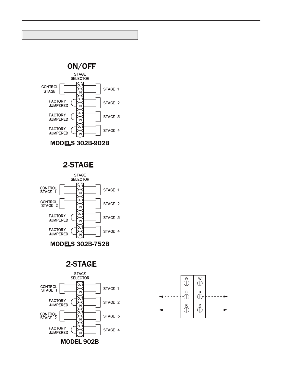
1. For Pool and Closed-Loop Water-Source Heat
Pump applications, your heater should be config-
ured to operate in an on-off firing mode. This
means that you will connect a single-pole control
to stage one of the CPW board. Then jumper the
remaining firing stages. For example, if your
heater is a Model 902B, you will jumper stages
two, three and four. Then your heater will either be
on at full fire, or it will be off.
2. For 2-stage controller connections, connect each
stage of the control to the corresponding stage of
the CPW board in the heater, i.e., stage 1 of the
heater to stage 1 of the control; stage 2 of the
heater to stage 2 of the control, as shown in Fig.
21 and 22. Set the operating control to the set-
point at which you want the heater to maintain.
Ensure that the sensing bulb of the control is at the
point in the system that will best maintain the tem-
perature you want. For example, when you are
heating a tank of water, you want the operating
control sensor bulb in the tank.
3. For single-stage controller connections, attach the
stage 1 connections on heater 1 to the tankstat per
Fig. 23.
Heater must be electrically grounded in accordance
with the NEC, and CSA C22.1 C.E.C. Part 1 in
Canada.
2-STAGE
TANKSTAT
STAGE 1
CONNECTION
STAGE 2 CONNECTION OR
STAGE 1 CONNECTION
OF HEATER 2
ATTACH STAGE 1 CONNECTIONS ON HEATER
TO STAGE 1 CONNECTION ON TANKSTAT.
ATTACH STAGE 2 CONNECTIONS OR
STAGE 1 CONNECTION OF HEATER 2
TO STAGE 2 CONNECTIONON TANKSTAT
AS SHOWN IN THE DIAGRAM.
Fig. 22: 2-Stage Tankstat
DANGER: SHOCK HAZARD
Make sure electrical power to the heater is discon-
nected to avoid potential serious injury or damage to
components.
Fig. 21: Wiring Connections