3 mod select circuit – Renesas 32176 User Manual
Page 56
32176 Group
Starter Kit User’s Manual M3A-2152
REJ10B0224-0310/Rev.3.10
Mar. 2008
Page 48 of 83
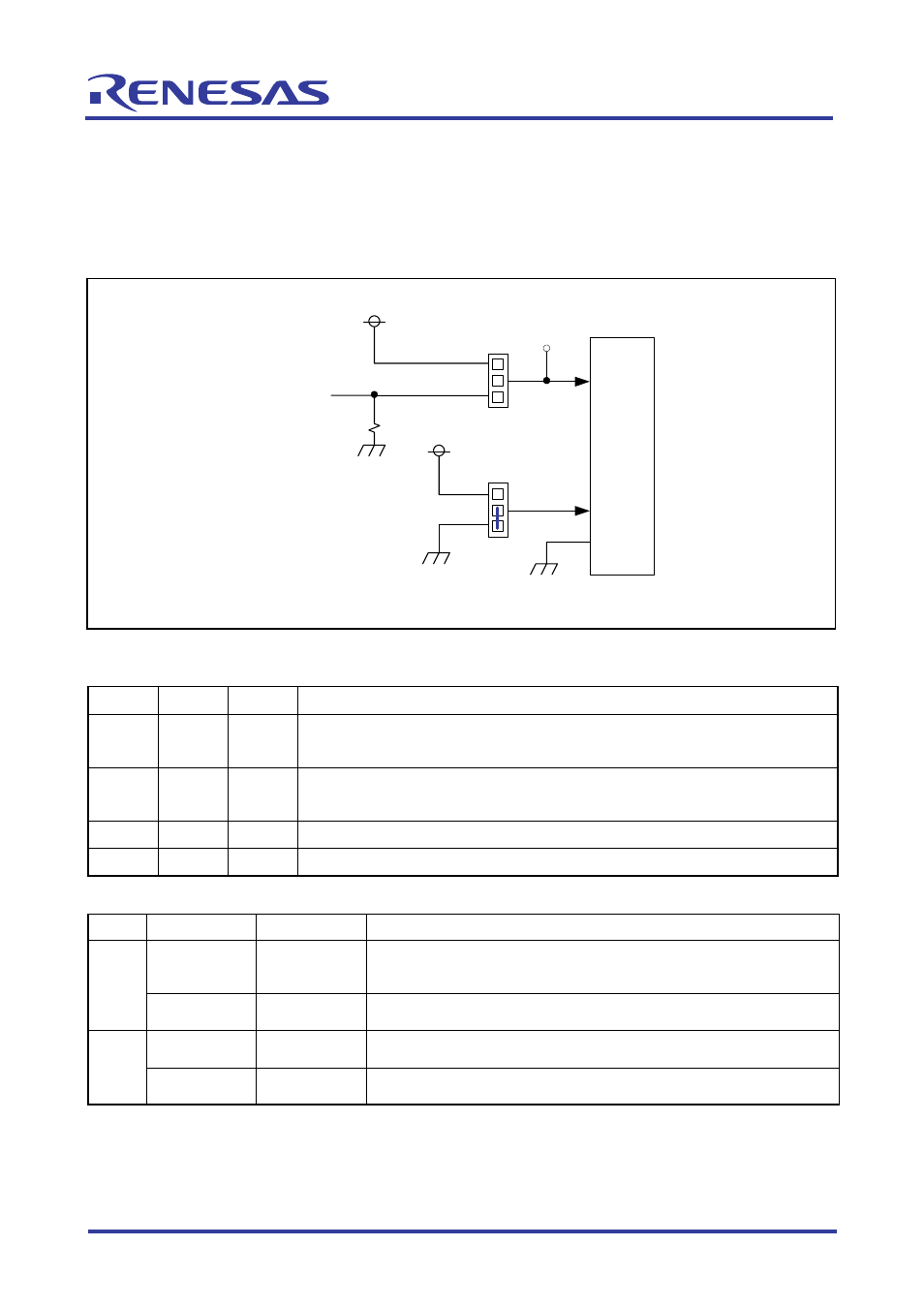
2.3 MOD Select Circuit
This circuit is used to set operation modes of the M32R/ECU. The MOD0 power supply is
configured in such a way that MOD0 is switched from the EXTMOD0 signal of extension connector
(CON2) by using a jumper (J8).
The MOD1 power supply defaults to 0 V. The MOD2 power supply is fixed to 0 V.
J2
U1
M32R/ECU
MOD1
3
1
2
VCC
J4
TX6
3
1
2
VCC
EXTMOD0
MOD0
MOD2
Note: TX6 is not mounted but it only has one pattern available.
Figure 2.3 MOD Select Circuit
Table 2.3 Operation Mode Settings
MOD0 MOD1 MOD2
Function
0 0 0
• When flash reprogramming is disabled: Single-chip mode
• When flash reprogramming is enabled: Flash rewrite + single-chip mode
1 0 0
• When flash reprogramming is disabled: Processor mode
• When flash reprogramming is enabled: Boot model + flash E/W enable
0 1 0
External
extension
mode
1 1 0
Settings
inhibited
Table 2.4 MOD Select Circuit (Jumper)
Name Default Condition
Description
{
Shorted
between 1–2
Controls MOD0 by EXTMOD0, unless control MOD0 by
EXTMOD0 sets MOD0 to 0
J4
Shorted
between 2–3
Sets MOD0 to 1
{
Shorted
between 1–2
Sets MOD1 to 0
J2
Shorted
between 2–3
Sets MOD1 to 1
Note: The J2 jumper is shorted by soldering.