2 hardware setup when m3a-2152g52 in use – Renesas 32176 User Manual
Page 22
32176 Group
Starter Kit User’s Manual M3A-2152
REJ10B0224-0310/Rev.3.10
Mar. 2008
Page 14 of 83
5.2 Hardware Setup when M3A-2152G52 in Use
5.2.1 M3A-2195 Power Supply Connection and Settings
The following shows how to set M3A-2195.
For more details, refer to M3A-2195 User’s Manual.
Power to the M3A-2195 SDI Interface Board can be fed from either a 5V DC power supply (5V) or
a 12 DC power supply (6-12V). Use the included 5V or 12V power supply cables to connect
M3A-2195 and a corresponding DC power supply.
The Connecting when Feeding Power to the M3A-21 is shown in Figure 5.4
Figure 5.4 Connecting when Feeding Power to the M3A-2195
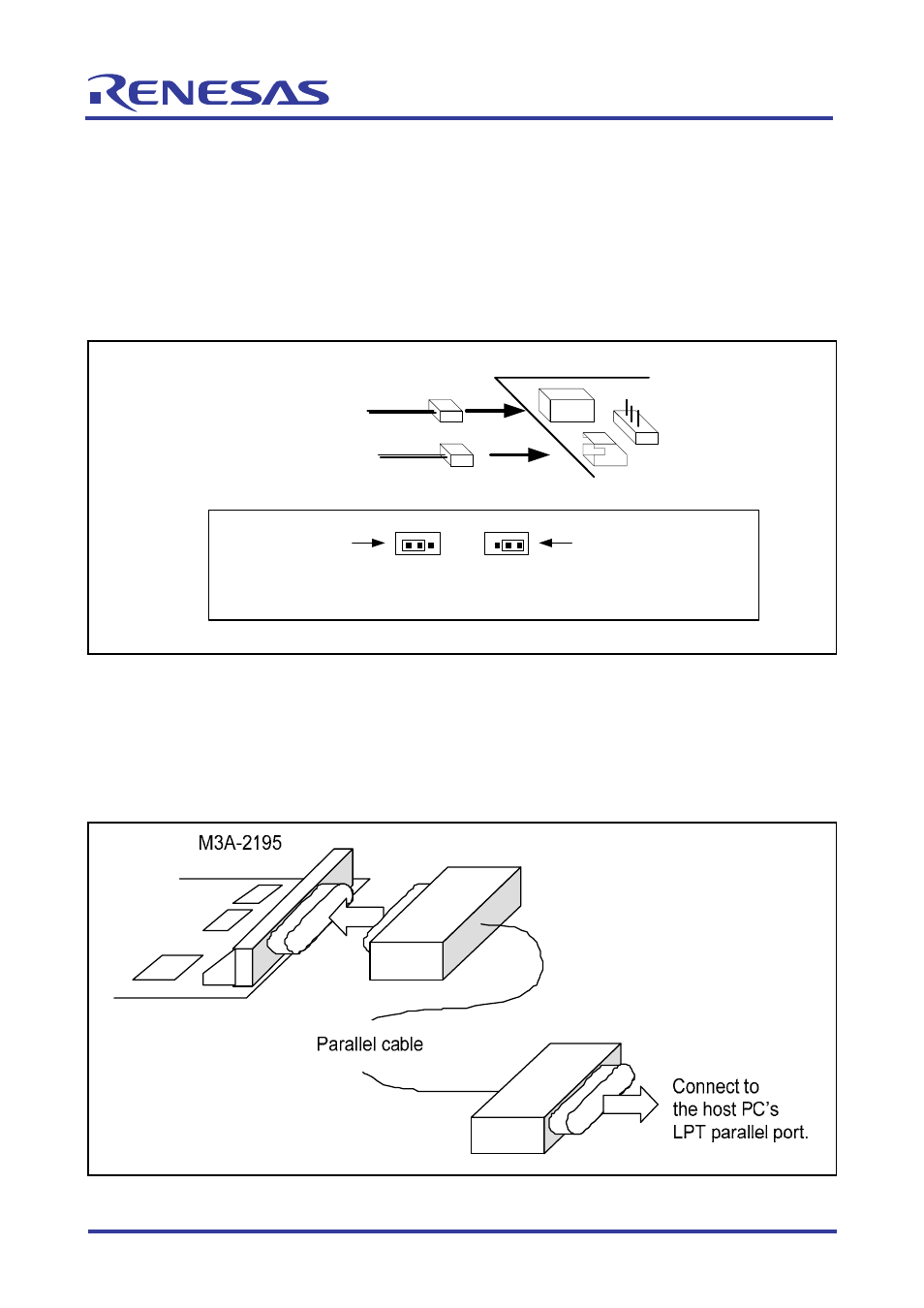
5.2.2 Connecting to Host PC
In order to control the M3A-2195 SDI Interface Board from M3S-KD32R installed in the host PC,
the host PC’s LPT parallel port and the M3A-2195’s J1 connector should be connected with the
parallel cable included in M3A-2195.
The Connecting the M3A-2195 and Host PC is shown in Figure 5.5
Figure 5.5 Connecting the M3A-2195 and Host PC
M3A-2195
J3
Feeding from 12V DC ( 6 - 12V )
Feeding from 5V DC ( 4.5 - 5.5V )
J4
JP1
3 JP1 1
3 JP1 1
Jumper connector
Jumper connector
When feeding from DC 12V(J3)
When feeding from DC 5V(J4)
(set as default when shipped from
factory)
Settings of JP1
or