Decay rate window, Figure 12-3. lqg/h-infinity decay rate window, H-infinity performance window – National Instruments Xmath Interactive Control Design Module ICDM User Manual
Page 99
Chapter 12
LQG/H-Infinity Synthesis
© National Instruments Corporation
12-5
Xmath Interactive Control Design Module
The weights
ρ
u, i
,
ρ
y, j
,
ρ
u
, and
ρ
y
are then replaced with noise variances
ν
u, i
,
ν
y, j
,
ν
u
, and
ν
y
. The noise level parameter in the main LQG/H
∞
window is related to the noise levels in this window by
υ = υ
y
/
υ
u
.
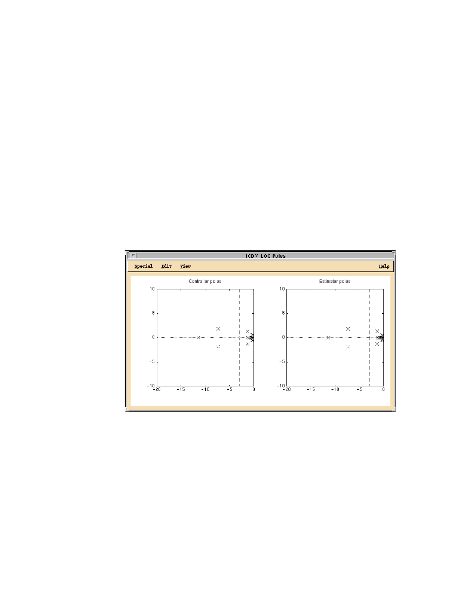
Decay Rate Window
The Decay Rate window is shown in Figure 12-3. From top to bottom, it
consists of:
•
A menu bar with entries Special, Edit, View, and Help.
•
A plotting area that contains two plots:
–
A plot of controller poles, and a vertical line indicating the
decay rate.
–
A plot of estimator poles, and a vertical line indicating the
decay rate.
Figure 12-3. LQG/H-Infinity Decay Rate Window
H-Infinity Performance Window
The H
∞ Performance window, shown in Figure 12-4, consists of, from top
to bottom:
•
A menu bar with entries Special, Edit, View, and Help.
•
A plot area that contains a plot of the closed-loop transfer matrix along
with the parameter
γ, which can be grabbed and dragged to a new