Setup and terminology, Standard lqg (all toggle buttons off) – National Instruments Xmath Interactive Control Design Module ICDM User Manual
Page 65
Chapter 7
LQG Synthesis
Xmath Interactive Control Design Module
7-4
ni.com
Setup and Terminology
The different modes are described using the following basic terminology:
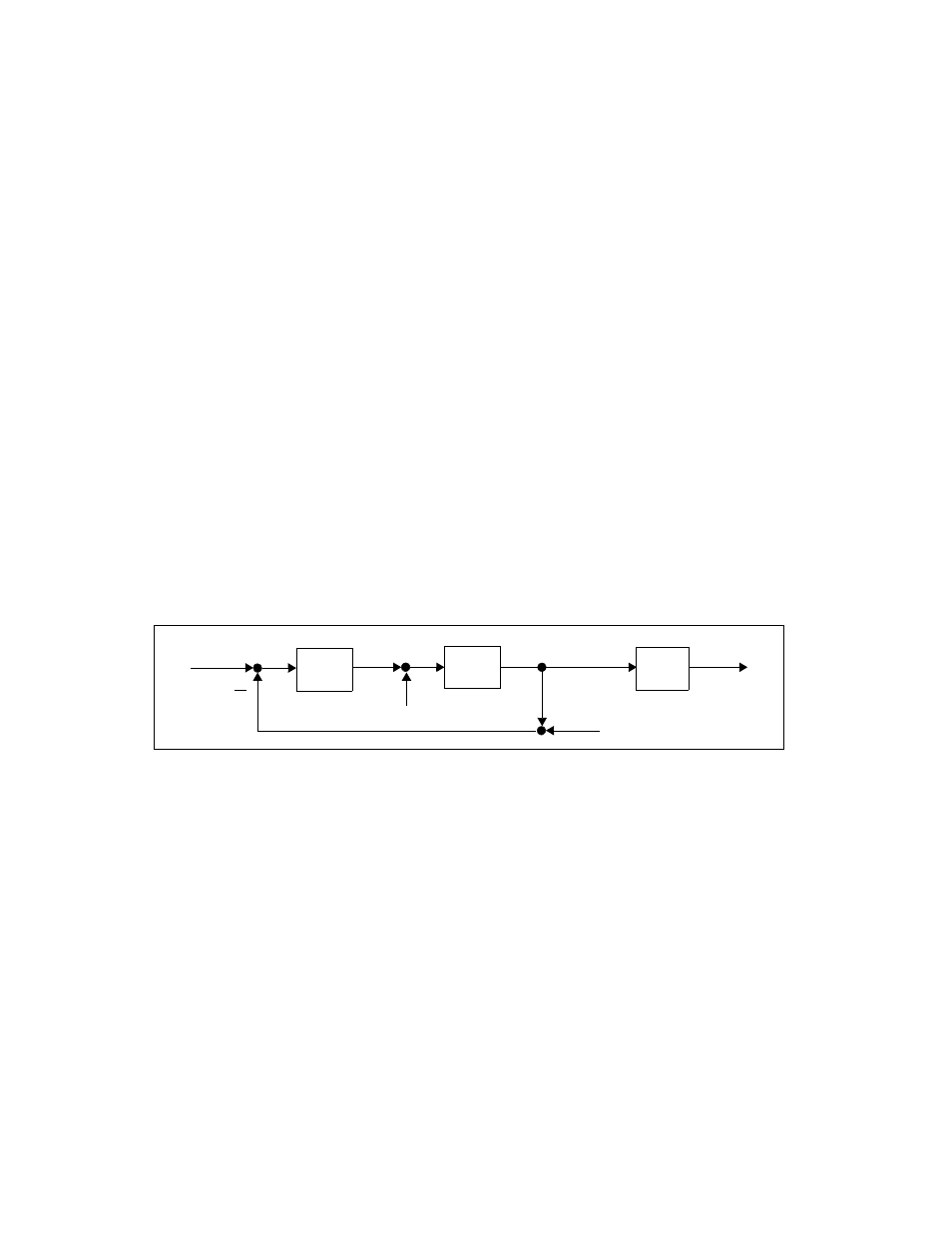
Figure 7-1 shows a block diagram with the basic setup for LQG synthesis,
where
u is the actuator signal (output of the controller)
w
proc
is an (input referred) process noise
y is the (plant) output signal
is the weighted output signal
w
sens
is a sensor noise
P is the plant transfer function
C is the controller transfer function
W is the output weight transfer function
The noises w
proc
and w
sens
are white; that is, they have constant power
spectral densities (PSDs). The parameter
υ is the ratio of the PSD of w
sens
to the PSD of w
proc
.
Figure 7-2. Block Diagram Showing the Basic Setup for LQG Synthesis
Standard LQG (All Toggle Buttons Off)
In LQG synthesis mode, the controller minimizes a weighted sum of the
steady-state actuator and output variance:
where E denotes expectation,
ρ is the Control cost parameter, and the
parameter
ν gives the ratio of the intensity of the sensor noise w
sens
to the
intensity of the process w
proc
noise (which are assumed to be white).
y
P u w
proc
+
(
)
=
u
C
–
(
) y w
sens
+
(
)
=
y˜
Wy
=
y˜
y
P(s)
r=0
W(s)
y
C(s)
u
w
proc
w
sens
J
E
t
∞
→
lim
ρu t
( )
2
y t
( )
2
+
(
)
=