Output signals, Table 3-11, Dio output specifications (xdio connector) – Nortech Systems Adept RS-232/TERM User Manual
Page 61: Table 3-11 on
Connecting Customer-Supplied Digital I/O Equipment
Adept SmartController User’s Guide, Rev. E
61
Output Signals
The XDIO connector handles output signals 0001 to 0008. Refer to
for output
specifications. The locations of the signals on the connector are shown in
. The XDIO connector provides separate positive and negative connections for
each channel (no internal common connections). This allows the choice of wiring for
current-sourcing or current-sinking modes.
shows two examples of different connections to the digital outputs on the
XDIO connector. The examples are negative common and positive common using the
internal 24V and ground connections.
Example 1: outputs 0001 to 0004 are shown with positive common.
Example 2: outputs 0005 to 0008 are shown with negative common.
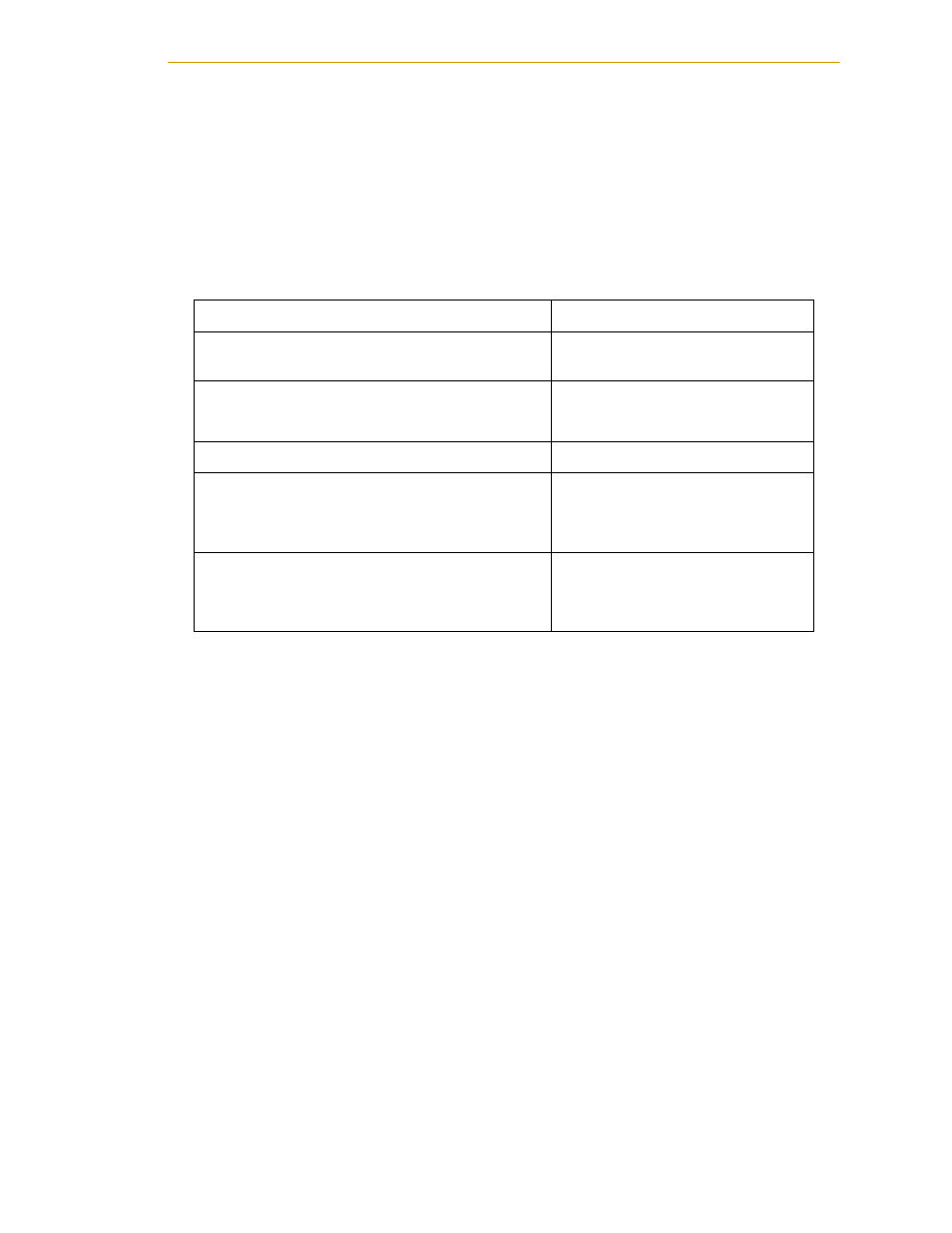
Table 3-11. DIO Output Specifications (XDIO connector)
Operating voltage range
0 to 24VDC
Operational current range, per channel
I
out
≤
100 mA, short-circuit
Protected
V
drop
across output in “on” condition
V
drop
≤
2.7 V at 100 mA
V
drop
≤
2.0 V at 10 mA
Output off leakage current
I
out
≤
600 µA
Turn on response time (hardware)
Software scan rate/response time
3 µsec maximum
16 ms scan cycle/ 32 ms max.
response time
Turn off response time (hardware)
Software scan rate/response time
200 µsec maximum
16 ms scan cycle/ 32 ms max.
response time