Installing the dsl interface cable, Installing the v.35 interface cable, Ee section – Patton electronic SmartNode 4830 Series User Manual
Page 37
Installing the VoIP IAD
37
SmartNode 4830 Getting Started Guide
3 • Hardware installation
Installing the DSL interface cable. The SmartNode Model 4830 comes with an option for a G.SHDSL or
ADSL interface. Use a straight-through RJ-11 cable to connect the DSL port.
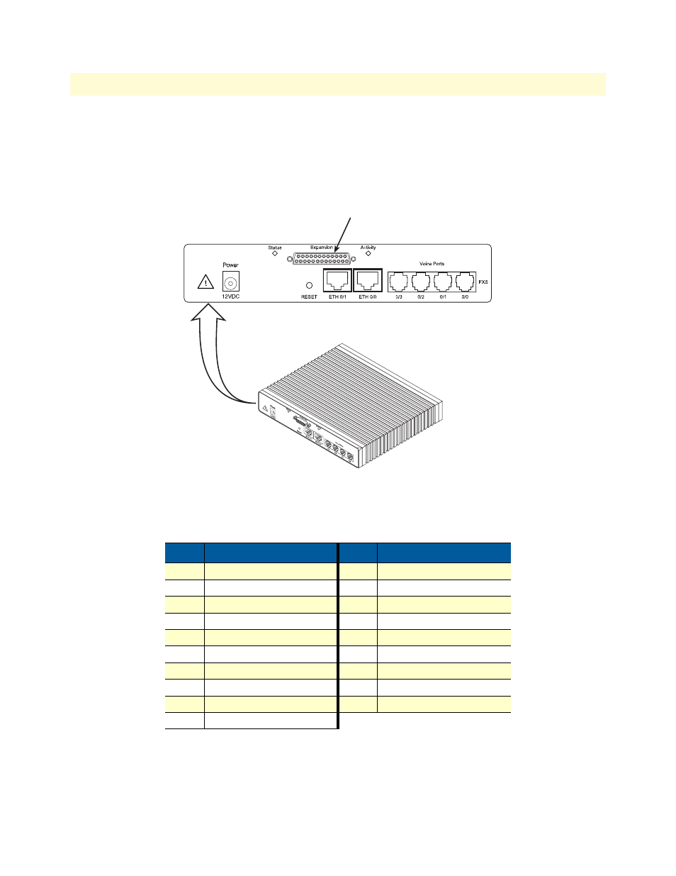
Installing the V.35 interface cable. The SmartNode Model 4830 comes with a V.35 interface presented on a
DB-25 female connector (see
Figure 16. Rear view of the SN4830 showing location of V.35 interface connector
The signal pin-outs for the Model 4830 V.35 interface are shown in
The SN4830’s V.35 interface is wired as a DTE. No DCE configuration is possible. If you are directly connect-
ing the SN4830’s V.35 interface to third-party equipment that cannot be configured as a DCE, you must use a
Table 7. Signal pin-outs for the V.35 interface on the SmartNode 4830
Pin
Signal
Pin
Signal
1
Frame Ground
12
TXCb
2
TXDa
14
TXDb
3
RXDa
15
RXCa
4
RTS
16
RXDb
5
CTS
17
RXCa
6
DSR
18
LL
7
Signal Ground
20
DTR
8
DCD
21
RL
9
RXCb
24
EXTCa
11
EXTCb
V.35 serial port connector