Powerware 9155 UPS20-30kVA User Manual
Page 44
44
UPS 20-30 kVA, 230 V 0/60 Hz output
User’s Guide
1026743
Revision B
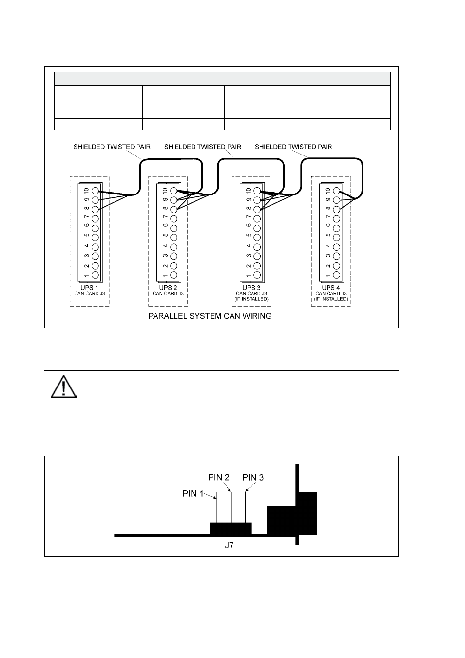
Figure 23 Communication cabling wiring
Note!
XSlot Hot Sync card has built-in termination resistor enabled by a jumper J7. The
default jumper setting without termination resistor is J7: Pin 2-3. The first and the
last UPS modules should have the termination resistor enabled by connecting Pins
1 and 2 with the jumper J7.
Figure 24 XSlot Hot Sync card and jumper settings: Resistor ON: PIN 1 and PIN 2 connected,
No resistor: PIN 2 and PIN 3 connected (default setting).
Communication Wiring Termination
From UPS 1 CAN card
To UPS 2 CAN card
To UPS 3 CAN Card
(If installed)
To UPS 4 CAN Card
(If installed)
J3-8 (L)
J3-8 (L)
J3-8 (L)
J3-8 (L)
J3-9 (H)
J3-9 (H)
J3-9 (H)
J3-9 (H)