Xslot hot sync card: installing and wiring – Powerware 9155 UPS20-30kVA User Manual
Page 43
43
UPS 20-30 kVA, 230 V 0/60 Hz output
User’s Guide
1026743
Revision B
6. First select “SETTINGS”, then “USER SETTINGS” and finally “SIGNAL INPUT” from LCD menu.
7.
Select “INPUT 1” (X44) or “INPUT 2“ (X4).
8. Browse the menu and select “FORCE BYPASS”.
9. Finally check that all the connections have been made correctly and test the fuctioning of
the bypass switch. Check also from the UPS that it goes to bypass mode.
XSlot Hot Sync card: installing and wiring
To enable parallel operation all the UPSs in the system need the XSlot Hot Sync card (see
Figure below) installed into an open XSlot on the front of the UPS (see chapter XSlot
communication).
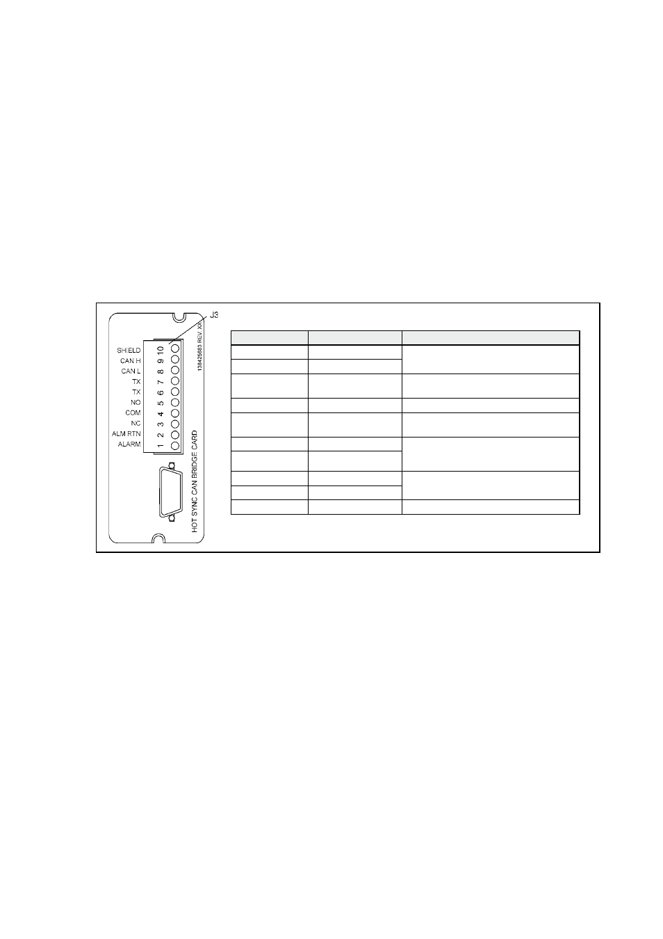
Figure 22 XSlot Hot Sync card and terminal interface
The Hot Sync communication wiring procedure should be done with shielded twisted pair
(STP) as presented in the figure below. The maximum length of the cable is 40 m with shield
connected to the terminal pin 10 from end of the both cables. Pay attention that you don’t mix
the polarity among the UPS modules.
Terminal J3
Name
Description
1
Alarm
Programmable UPS alarm. Activated by a
remote dry contact closure
2
Alarm Rtn
3
Alarm Relay NC
Normally-closed contact opens when UPS
is on bypass.
4
Alarm Relay Com
Bypass contact return.
5
Alarm Relay NO
Normally-open contact closes when UPS
is on bypass.
6
TX
Remote Monitor Panel (RMP). Relay
Interface Module (RIM), or Supervisory
Contact Module (SCM) Connections.
7
TX
8
CAN L
Controller Area Network (CAN) Input for
parallel operation.
9
CAN H
10
Shield