Maintenance bypass switch (mbs) operation – Powerware 9155 UPS20-30kVA User Manual
Page 36
36
UPS 20-30 kVA, 230 V 0/60 Hz output
User’s Guide
1026743
Revision B
Maintenance bypass switch (MBS) operation
The maintenance bypass switch may be as standard or as optional in your system depending
on the ordered configuration. The operation of the MBS is allowed for a trained person only
who is familiar with the UPS behaviour and functions. The full UPS wiring diagram with a MBS
switch is presented in the installation part of the manual. The MBS is located in the bottom of
the UPS near power terminals
Note!
The MBS consist of three switches and failure to understand the correct sequence
may drop the critical load.
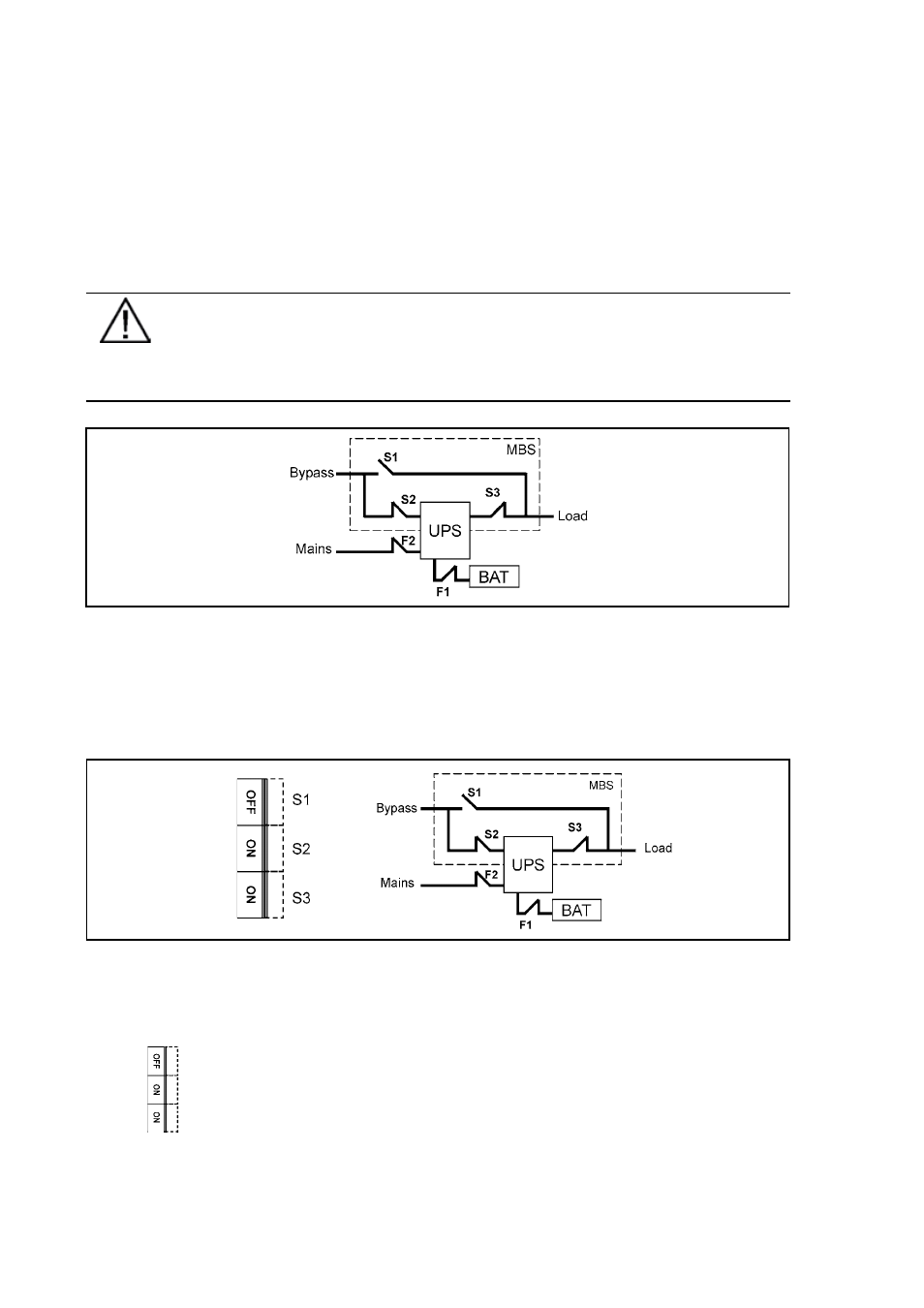
Figure 16 The normal positions of the three MBS switches.
Turn UPS from normal mode to maintenance bypass mode (service bypass mode)
The procedure to turn the UPS to maintenance bypass switch is described below.
Figure 17 The normal (UPS supplying the load) positions of the three MBS switches.
No break transfer from normal mode to Service Bypass:
1.
The normal start position should be following: