Power cables and protective fuses – Powerware 9155 UPS20-30kVA User Manual
Page 17
17
UPS 20-30 kVA, 230 V 0/60 Hz output
User’s Guide
1026743
Revision B
The UPS unit has the following power connections:
Three-phase (L1, L2, L3), Neutral (N) and protective earth (PE) connection for the rectifier
input (Note: N is only an open tie point)
Single-phase (L1), Neutral (N) and protective earth (PE) connection for the bypass input (N
is common for rectifier and bypass inputs)
Single-phase (L1), Neutral (N) and protective earth (PE) connection for the load output
Plus (+), minus (-) and protective earth (PE) connection for the external batteries
Note!
The rectifier requires a Neutral to operate. It’s connected internally from the bypass
terminal to the rectifier, see wiring diagram.
Note!
Care needs to be taken to ensure that the input supply neutral reference is not
disconnected whilst the UPS is in service.
Power cables and protective fuses
Always use copper cable types to fit terminals with approx. 1. Nm torque for different load
currents. The Cu cable sizing is based on multi-core cables laid in conduits/trunkings on the
wall or on the floor (installation procedure C), ambient temperature 2°C, PVC insulation,
surface temperature up to 70°C. Cables of several UPS can be installed in parallel to each other.
Standards SFS 6000--2 (2002) and IEC 60364--2 (2001-08) “Electrical installations of
buildings” with normal 1.7 x Neutral conductor rating for IT loads are used as a sizing guide.
For any other conditions, size the cables according to the local safety regulations regarding
installation environment, appropriate voltage and currents of the UPS.
Fuses are sized according to local safety regulations, appropriate input voltage and the rated
current of the UPS. Therefore, protect the input and bypass cables with gG (gL) fuses or B-C-D
type of circuit breakers against overload and short-circuit.
Contact the manufacturer’s authorised agent or the local office for assistance at fuse and cable
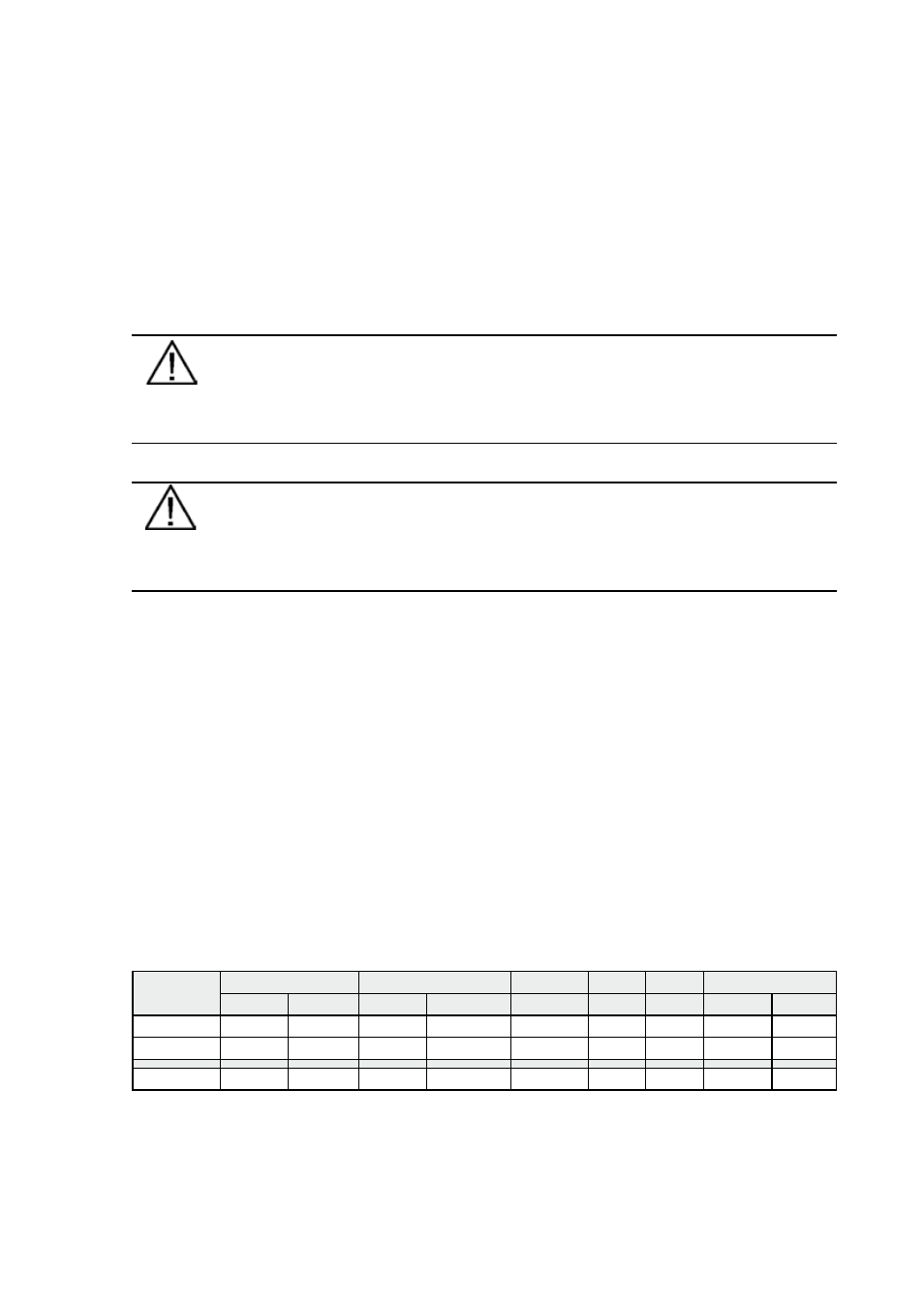
sizing. Refer to the recommended cable and fuse ratings in the below table.
UPS rating
Input
Bypass
Load
PE
Battery
Fusing
Cable
Fusing
Cable/L1-N Cable/L1-N I nom
Cable
Cable
Fusing
20 kVA
3x35 A
4x10 mm² 100 A
35 mm²
35 mm²
87,0 A
16 mm² 16 mm²
2x125 A
30 kVA
3x50 A
4x10 mm² 160 A
70 mm²
70 mm²
130,4 A 35 mm² 16 mm²
2x125 A
Maximum
4x35 mm²
95 mm²
95 mm²
35 mm² 35 mm²
Table 2 Minimum Cable and fuse ratings for the different UPS ratings with installation procedure C
•
•
•
•