Step 3: connecting the audio cable, Step 2: connecting the video cable – Philips G-CODE 7819901511 User Manual
Page 11
10
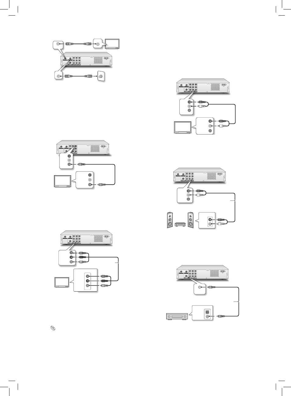
Step 3: Connecting the Audio
Cable
Option 1 Using Composite Cable
Use the audio (red and white) ends of a composite cable to
connect the AUDIO OUT jack on the DVD recorder to the
AUDIO IN jack on the television.
TV
VIDEO
R
L
R
L
VIDEO IN
AUDIO IN
Option 2 Connecting to a Stereo Audio Amplifier or
Receiver
Use the audio (red and white) ends of a composite cable to
connect the AUDIO OUT jack on the DVD recorder to the
AUDIO IN jack on a stereo amplifier or a receiver.
Audio cable
IN
RIGHT
LEFT
VIDEO
R
L
Stereo audio amplifier
or receiver
Option 3 Connecting to a Digital Audio Device
Use a coaxial cable (not supplied) to connect the DIGITAL
OUT (COAXIAL) jack on the DVD recorder to the
coaxial digital input on a stereo amplifier or a receiver.
IN
OPTICAL
COAXIAL
COAXIAL
Digital Out (Optical)
DIGITAL AUDIO DEVICE
Coaxial digital cable
T V
RF OUT
RF IN
Wall
RF IN
..........................................................................................
Step 2: Connecting the Video
Cable
Option 1 Using Composite Cable
Use the video (yellow) end of a composite cable to
connect the VIDEO OUT jack on the DVD recorder to the
VIDEO IN jack on the television.
TV
VIDEO
R
L
R
L
VIDEO IN
AUDIO IN
Option 2 Using Component Cable
Use a component video (with green, blue and red ends)
cable to connect the COMPONENT OUT jack on the
DVD recorder to the COMPONENT IN jack on the
television.
Component video cable
Y
CB / PB
CR / PR
COMPONENT IN
Y
CB / PB
CR / PR
T V
If your television supports ‘Progressive Scan’ mode,
you may adjust the ‘Video Output’ setting accord-
ingly in setup menu for better results. Go through
SetupSystemVideo Outpu, and select ‘Progres-
sive’.