Pioneer Plasma Display Monitor 502MX User Manual
Page 26
26
Special Installation (Mounting to fittings)
3.4 Special Installation
The unit can be hung from or embedded in a wall, but such special installations impose additional limitations on
operating temperatures and other operational factors.
Examine installation methods and the ambient conditions for your installation site, and refer to sections 3.1 to 3.3 in
this manual.
Measurements discussed in this manual assume the following conditions:
• A 100 % white input is supplied.
• Sufficient aging has been completed.
Make all measurements under identical conditions. The aging period required for correct measurement will be about
two and a half hours, depending on the space available at the installation site.
3.4.1 Mounting to fittings
Observe the following guidelines when mounting the unit to fittings.
Notes 2 to 7 apply to all cases of mounting to fitting.
1 When mounting the unit, make sure that there are no objects around it within a distance of 300mm.
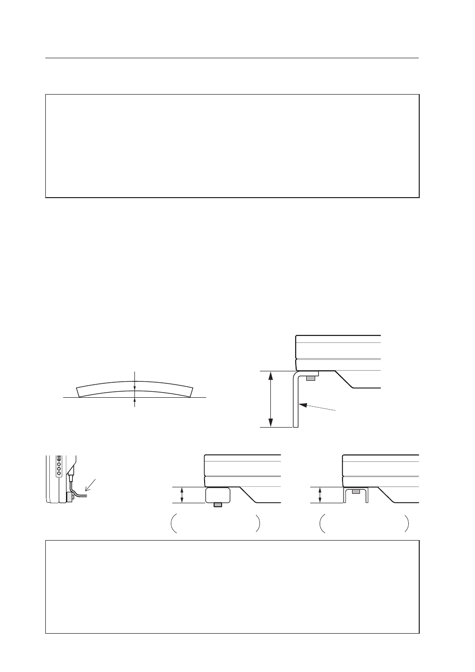
2 Any unit deformation/warping occurring as a result of installation should be less than 4 mm.
3 Never block or cover openings, aside from those shown as blocked in the illustrations on the following page.
4 The fittings should have a thickness of less than 20 mm. (This limit does not apply to fittings in examples 2, 4, 6
and 8 on the following page.)
5 L-shaped fittings should have a thickness of less than 100 mm.
6 The strength of the fittings should be adequate to bear the weight of the display.
7 Take precautions to avoid sharply bending the power cable.
✩ Operating environment for standard installation
• Ambient Temperature:
0 to 40 °C (examples 1 to 4)
✩ Operating environment for vertical installation
0 to 40 °C (vertical installation: examples 5 to 8)
✩ Operating temperatures for Upside-Down Installations (possible only for attachment examples 2 and 3)
• Ambient temperature:
0 to 40 °C
The operating temperature restrictions for the speaker system (PDP-S03-LR) are the same regardless of whether
installation is horizontal or vertical.
Maximum allowable deformation/warping is 4 mm.
4 mm MAX
Less than
100 mm
L-shaped fitting
Arrange the power
cable so that minimum
stress is placed on it.
Less than
20 mm
Less than
20 mm
No thickness limitations
in examples 2, 4, 6 and 8
on the following page.)
No thickness limitations
in examples 2, 4, 6 and 8
on the following page.)