Pioneer Plasma Display Monitor 502MX User Manual
Page 10
10
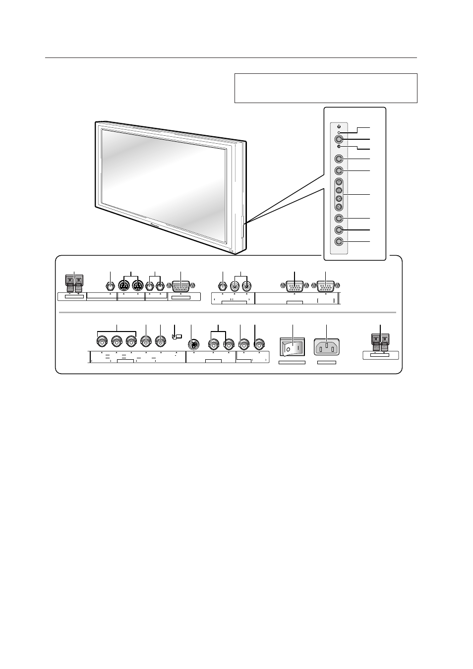
2.3 Controls and Connectors
Controls and Connectors
1 STANDBY/ON indicator
Red when the display is in standby mode; turns green
when the display is operational.
2 STANDBY/ON button
Turns main power on or off.
3 KEY LOCK/UNLOCK switch (hidden)
Renders the operation panel and remote operative or
inoperative.
4 INPUT button
Used to select inputs.
5 MENU button
Used to display the menu screen.
6 ADJUST (
5∞32
) buttons
Used to move the cursor on the menu screen or to
increase/decrease adjustment values.
7 SET (select) button
Used to select an adjustment item on the menu screen
or to change settings.
8 SIZE button
Used to manually change screen size.
9 DISPLAY button
Used to view input and settings conditions.
0 SPEAKER
Output terminal for a right-hand external speaker.
Connected to speakers of 8 to 16
Ω
impedance.
- AUDIO OUTPUT (Stereo mini jack)
Used to output the sound from a device connected to the
display to a device such as an AV amplifier.
= Combination Input and Output Terminals
Used for simultaneous control of various units.
(Refer to 5.6 “Combination Connection”.)
Please use a Mini DIN 6-pin cable (straight, all pins wire
bound; this is readily available on the market) as the
connector cable.
(NOTE) No ABL linkage function is provided.
These terminals are incompatible with multi-
projections such as the RM-V4000V.
When the main power is off, there is no output.
RS-232C
75
Ω
2.2k
Ω
SPEAKER
8
Ω
~16
Ω
COMBINATION
CONTROL
AUDIO OUTPUT
IN
OUT
IN
OUT
INPUT 3/4
INPUT 1/2
R
L
ANALOG
R G B
INPUT 4
AUDIO INPUT
OUTPUT
ANALOG
R G B
MAIN POWER
AC INLET
R
HD
R
B
G
VD
Y
INPUT 2
INPUT 3
ON SYNC
OUTPUT
INPUT 1
VIDEO
S-VIDEO
Y
C
OFF
ON
C
R
/P
R
C
B
/P
B
INPUT 1
H/V SYNC
SPEAKER
8
Ω
~16
Ω
L
STANDBY/ON
INPUT
MENU
ADJUST
SET
SIZE
DISPLAY
2
4
3
5
6
7
8
9
1
0
-
@
!
$
%
=
~
#
_
^
+ ¡
™
£
¢
)
(
*
&
(at the rear of the
main unit)
NOTE
When the optional plasma display speakers are attached, it is
not possible to use the operation panel on the display.