Installation conditions – Pioneer Plasma Display Monitor 502MX User Manual
Page 19
19
3.2.2 Calculating heat quantity
As a curtesy to our customers, we have included the power formula to calculate the air conditioning needs.
For power consumption, allow for 500 W
≠
500 VA per unit.
Since most of the power consumed is transformed into heat, power consumption may be regarded as roughly equal to
generated heat.
1 Conversion to calories
[W]
×
0.86 = [kcal/h]
Heat generated per display: 500 W
×
0.86 = 430 kcal/h
2 Conversion to British Thermal Units
[W]
×
3.41 = [BTU/h]
Heat generated per unit: 500 W
×
3.41 = 1705 BTU/h
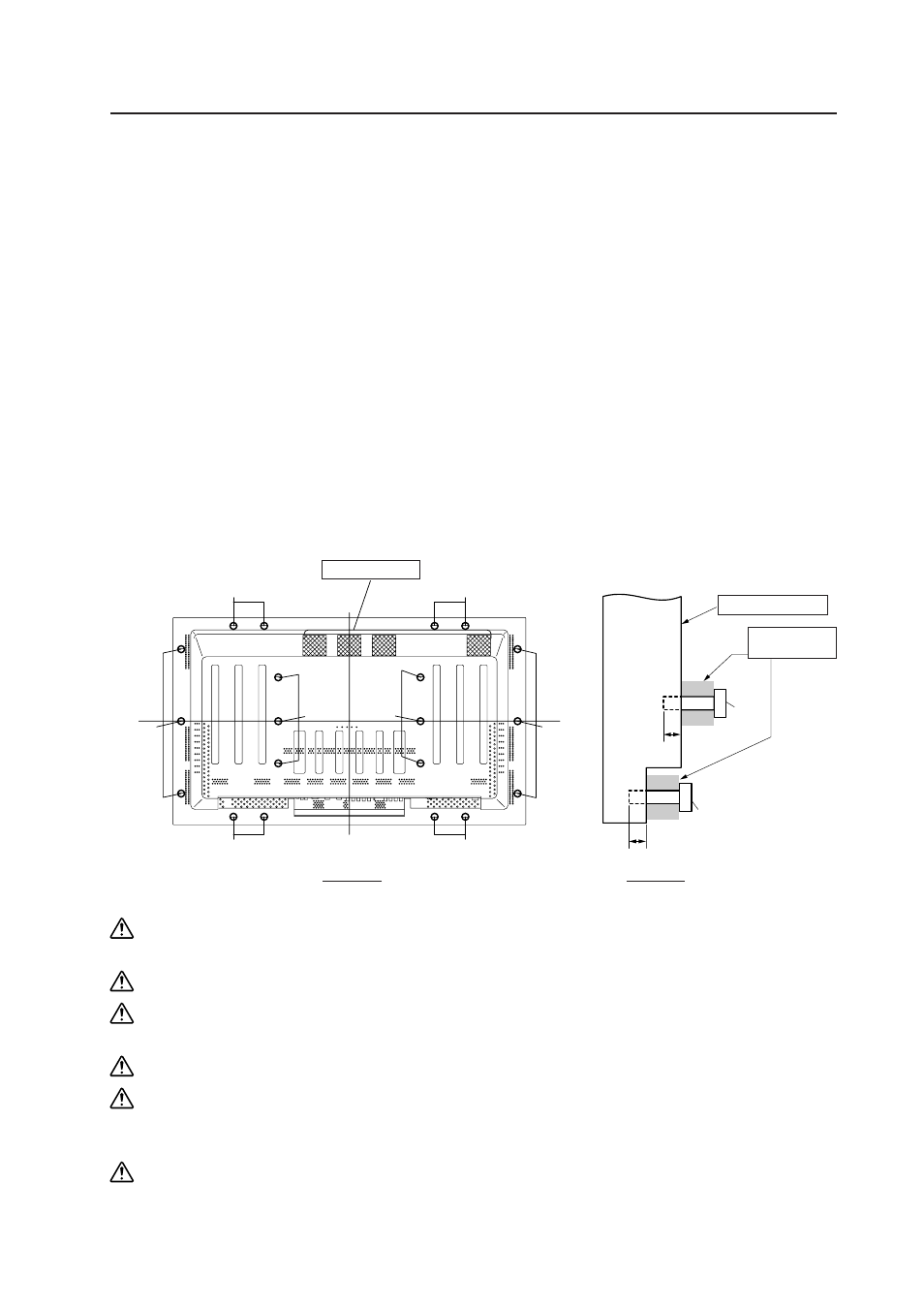
3.2.3 Product mounting holes
We recommend using mounting hardware available from Pioneer. If you use other mounting hardware items, mount
them to the unit using the M8-bolt holes provided in the unit. Remove the hole rivets, depending on the particular
mounting hardware used. Tighten the bolts with a torque between 50 and 80 kg/cm. Applying a torque beyond these
limits may lead to internal component failure.
• Locations of useable mount holes are shown below. (Caps or plugs can be removed by turning them with a coin or
other device.)
Installation Conditions
Always use a minimum of 4 mounting holes, evenly distributed on opposite sides of both the horizontal and
vertical center lines.
Use bolts that can be driven 12 to 20 mm into holes "a" or "b", as shown in the Side View above.
Do not block or cover air outlets and openings for ventilation on the rear panel.
Take precautions to prevent soiling walls behind the product with exhaust air discharged from the air outlets.
This unit incorporates glass components. Install only on flat surfaces.
Always turn every bolt by hand 2 or 3 times and check to make sure it is straight, then tighten it using a tool.
Do not over tighten bolts.
Do not use loctight or similar bonding products.
Please make sure that you use M8 (P=1.25) bolts. (other types of bolt cannot be used).
Air holes (Fan)
Hole "b"
Center
Line
Rear View
Mounting Surface
Bolt
12 to 20 mm
Bolt
Side View
The main
unit
Hole "a": in 6 locations
Hole "b": in 14 locations
Hole "b"
Hole "b"
Hole "b"
Hole "b"
Hole "b"
Hole "b"
Hole "a"
Hole "a"
Center
Line
Hole "a"
Mount
hardware, etc.
12 to 20 mm