Troubleshooting & repair, Diode module removal and replacement, Warning – Lincoln Electric MULTI-WELD SVM151-A User Manual
Page 97: Removal, F-57, Figure f.15 – diode module mounting details
TROUBLESHOOTING & REPAIR
F-57
F-57
MULTI-WELD 350
MUL
TI-WELD 350
LIN
COLN
ELECTR
IC
AMPS
VOL
TS
A
V
EL
EC
TR
OD
E
INP
UT
W
OR
K
CH
OP
PE
R
TE
CH
NO
LO
GY
+
-
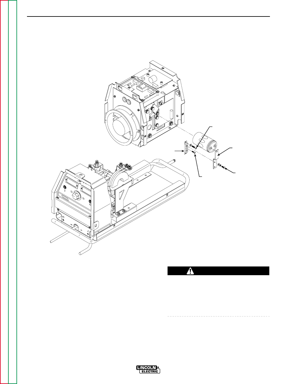
3/16"
ALLEN-HEAD
SCREWS (2)
DIODE
MODULE
CAPACITOR
NEGATIVE
STRAP
MOUNTING
BOLTS (2)
9/64"
ALLEN-HEAD
SCREW (1)
FIGURE F.15 – DIODE MODULE MOUNTING DETAILS
DIODE MODULE REMOVAL AND REPLACEMENT
REMOVAL
Refer to Figure F.15.
1.
Set the CC/CV power switch to OFF.
2.
Remove input power to the machine.
ELECTRIC SHOCK can kill.
Disconnect input power before removing the
case cover and performing tests or making
repairs to the machine.
WARNING
See also other documents in the category Lincoln Electric Tools:
- AIR VANTAGE IM10065 (54 pages)
- PRECISION TIG IM936 (44 pages)
- MAGNUM IM887 (20 pages)
- X-Tractor 1GC (4 pages)
- CAN-M393 (3 pages)
- CV ADAPTER IM309-D (46 pages)
- Idealarc 250 (2 pages)
- L12810-1 (4 pages)
- IM359-G (34 pages)
- OUTBACK 145 (34 pages)
- 4.1 (20 pages)
- CV-655 (47 pages)
- K1308-12 (4 pages)
- IM803-B (31 pages)
- LN-25 IM10092 (39 pages)
- PRECISION TIG 275 IM702-A (46 pages)
- Pipeliner 200D (4 pages)
- POWER FEED 10M SINGLE/DUAL SVM172-A (151 pages)
- CLASSIC 300G IM659-B (33 pages)
- INVERTEC V350-PRO IM708 (38 pages)
- Magnum 300 and 400 GMA Gun & Cable Assemblies K514 (29 pages)
- CLASSIC III 10061 (34 pages)
- 347 AC-DC (3 pages)
- INVERTEC IM958 (38 pages)
- Cool-Arc 40 (2 pages)
- IM795 (39 pages)
- Excalibur 11018M MR (1 page)
- METALUX 396T8HO (2 pages)
- MIG PAK HD IM822 (39 pages)
- VINTAGE 400 (CE) IM889-A (49 pages)
- IM481-B (35 pages)
- POWER MIG SVM157-A (91 pages)
- 600-I (2 pages)
- 4R90 (8 pages)
- IM613-B (54 pages)
- pmn (35 pages)
- RANGER 250 IM919 (49 pages)
- Welding Helmet (4 pages)
- IM355-C LN-9F GMA (70 pages)
- IM628 (17 pages)
- COOL ARC 35 IM959 (22 pages)
- POWER MIG 215 (35 pages)
- LN-25 PRO IM901-A (44 pages)
- METALUX 248 (2 pages)
- MAGNUM PCT125 (25 pages)