Troubleshooting & repair, Warning, Digital meter removal procedure – Lincoln Electric MULTI-WELD SVM151-A User Manual
Page 80: F-40
TROUBLESHOOTING & REPAIR
F-40
F-40
MULTI-WELD 350
DIGITAL
METER
OUTPUT
CONTROL
POTENTIOMETER
BEZEL
LENS
KNOB
SPACER
SEAL
HO
T STA
RT
ARC FO
RC
E
OTE
4
4
2
2
0
6
6
10
5
4
3
2
6
10
9
8
7
CC
SL
OP
E
PIP
E
STIC
K 701
8
GO
UG
E
L111
41-2
CC
CV
OFF
AMPS
VOL
TS
A
V
MUL
TI-WELD 350
LINCOLN
ELECTRIC
EL
EC
TR
OD
E
IN
PU
T
WO
RK
CH
OP
PE
R
TE
CH
NO
LO
GY
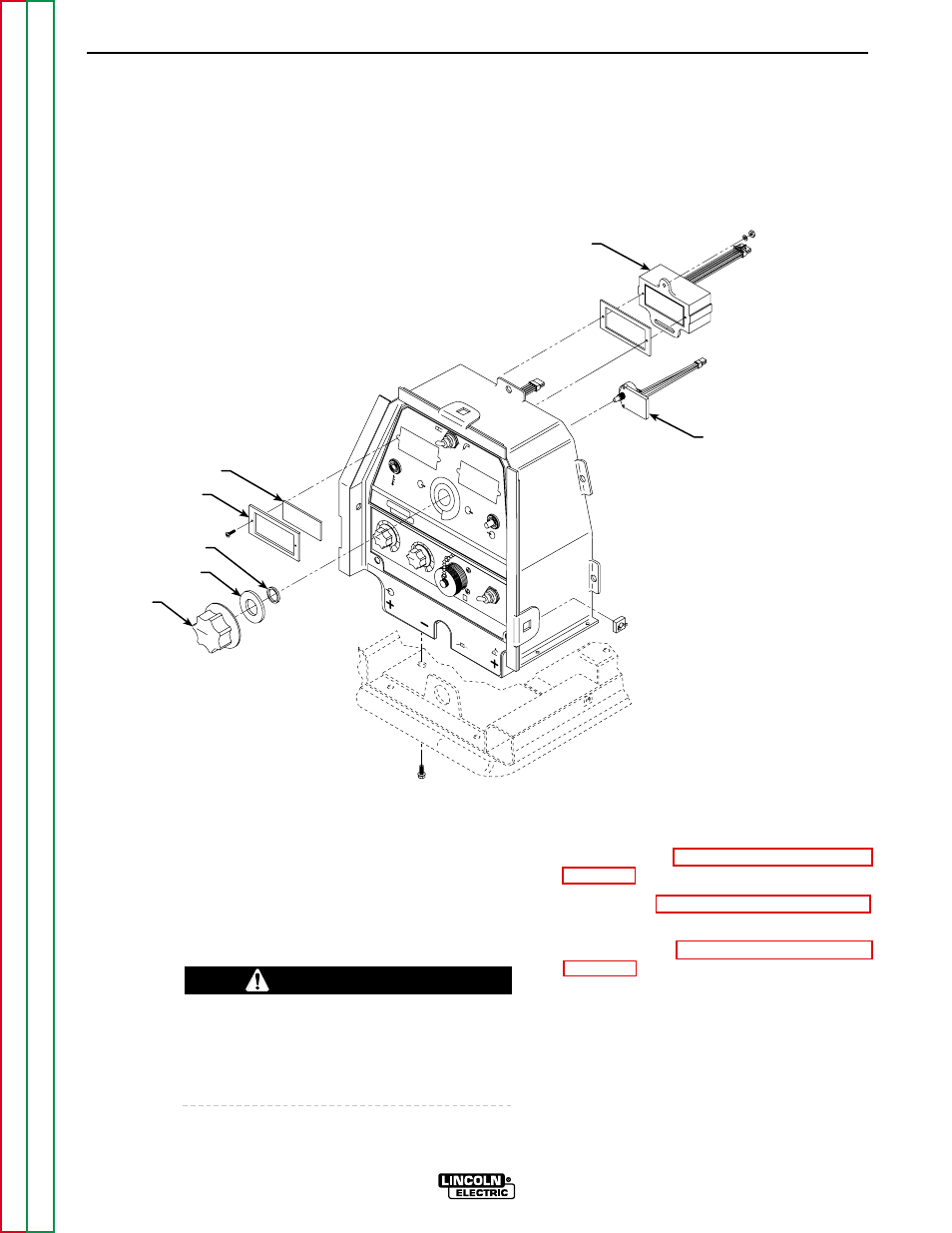
FIGURE F.9 – DIGITAL METER AND POTENTIOMETER DETAILS
AMPS/VOLTS DIGITAL METER AND POTENTIOMETER
REMOVAL AND REPLACEMENT (CONTINUED)
DIGITAL METER REMOVAL
PROCEDURE
Refer to Figure F.9.
1.
Set the CC/CV power switch to OFF.
2.
Remove input power to the machine.
ELECTRIC SHOCK can kill.
Disconnect input power before removing the
case cover and performing tests or making
repairs to the machine.
3.
Perform the Case Cover Assembly
Removal procedure.
4.
Perform the Power Capacitor Discharge
procedure.
5.
Perform the Case Front Assembly
Removal procedure.
6.
Using the 5/16" nut driver, remove the
seven screws from the control box rear
panel.
WARNING