Installation, Safety precautions, Quick-connect “pig-tails – Lincoln Electric MULTI-WELD SVM151-A User Manual
Page 9: Attachment and arrangement of “pig-tails, Warning
Read this entire installation section before you
start installation.
SAFETY PRECAUTIONS
ELECTRIC SHOCK can kill.
• Do not touch electrically live
parts or electrodes with your
skin or wet clothing.
•
Insulate yourself from the
work and ground.
• Always wear dry insulating
gloves.
Only qualified personnel should install, use, or ser-
vice this equipment.
QUICK-CONNECT “PIG-TAILS”
The Multi-Weld 350 is factory provided with two 21
in.(53 cm) long 2/0 AWG (70 mm
2
) “pig-tail” cables.
Their 0.5" (13 mm) hole lug ends are routed through
the “INPUT +” (on back) and “ELECTRODE +” (on
front) cable channels of the Converter. They are
attached to the bottom-accessed covered cable con-
nection studs.
Attach the preferred standard, user-provided Quick-
connect terminal (such as Lincoln Twist-Mate or Tweco
2-MPC type) to the cut-off end of these cables. Use the
female connector on the “ELECTRODE +” cable and
the male connector on the “INPUT +” cable.
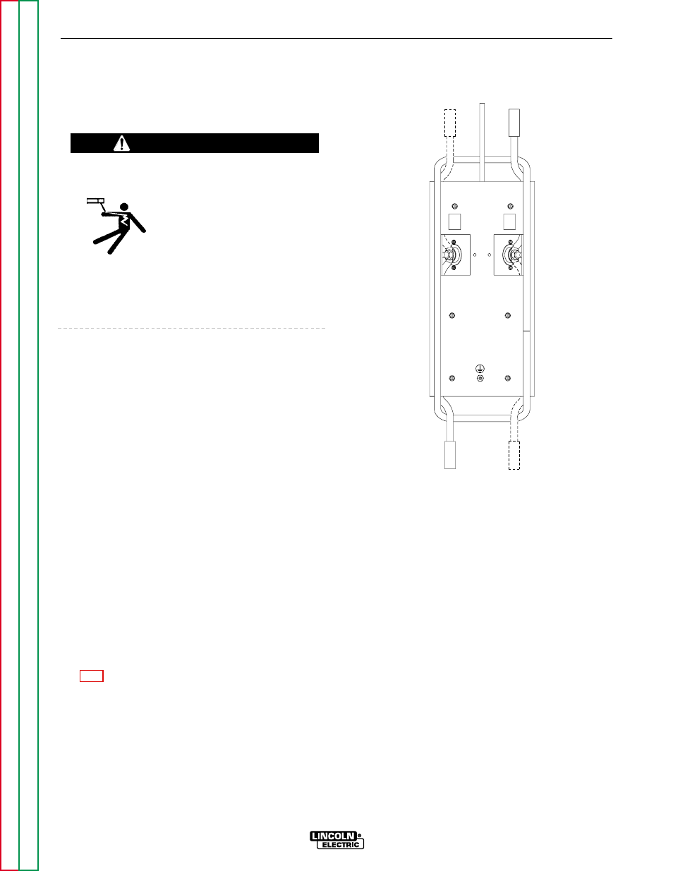
ATTACHMENT AND
ARRANGEMENT OF “PIG-TAILS”
To best suit the desired inter-connection of the
Converters, the “pig-tail” cables may be routed into the
front or back cable channels. For single or double “pig-
tail” cables, route through the bottom-accessed cov-
ered cable connection studs. (See Figures A.1
and B.1.)
To connect the “pig-tail” cables to the Converter:
1.
Stand the Converter vertically on its rear handle
and skid to gain access to the bottom stud covers.
Then remove the two 0.25"(6.3 mm) screws secur-
ing each cover and fold out the cover insulation.
2.
Route the appropriate “pig-tail” cable lug ends
under the skid rail (for strain-relief) through the
desired front and/or rear corner channels to the
exposed 0.5" (13 mm) stud. Remove the flange
nut with a .75" (19 mm) wrench.
NOTE: Input supply cable(s) must connect through
“INPUT +” labeled channels, and output weld cable(s)
must connect through “ELECTRODE +” labeled
channels.
3.
Slip the “pig-tail” cable lug(s) over the stud and re-
secure the flange nut. Make sure that the lug(s) do
not touch any sheetmetal of the stud housing. Fold
back the cover insulation and replace the stud
cover.
A-3
A-3
INSTALLATION
MULTI-WELD 350
WARNING
BOTTOM VIEW
TO ELECT.
TO ELECT.
TO
WORK
TO POWER
SOURCE
TO POWER
SOURCE
+
INPUT
+
ELECTRODE
ELECT.
+
ELECT.
+
+
IN
+
IN
FIGURE A.1 – PIG-TAIL CONNECTIONS