Operation, Front panel controls – Lincoln Electric MULTI-WELD SVM151-A User Manual
Page 18
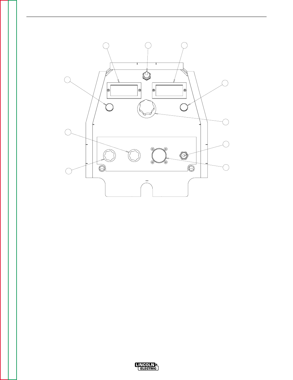
FRONT PANEL CONTROLS
The numbered items of Figure B.2 match the num-
bered items described below:
These few instruments and controls are basic to the
operation and monitoring of the Converter. They are
intuitively laid out so that the panel left side is weld cur-
rent related, and the right side is weld voltage related:
(1) Input Power/ Mode Switch has three positions:
Center is OFF, which shuts off input power to the
Converter.
• Neither displays nor output is on if in OFF
position.
Left is on for CC (constant current) welding mode.
• Only AMPS digital meter is lit, displaying the
preset current setting.
• Output will be on at o.c.v. (open circuit voltage).
Right is on for CV (constant voltage) welding
mode.
• Only VOLTS digital meter is lit, displaying the
preset voltage setting.
• Output will be on at the output voltage setting.
(2) Output Control has 3-3/4 turn resolution with slip-
clutch to prevent control pot damage.
In CC mode it presets AMPS (30-350A range)
when not welding and adjusts actual arc current
while welding.
In CV mode it presets VOLTS (15-40v range)
when not welding and adjusts actual arc voltage
while welding.
(3) AMPS Digital Meter is a 3-1/2 digit LED meter
which displays:
Preset AMPS in CC mode when not welding.
“Blank” in CV mode when not welding.
Actual AMPS while welding in both CC and CV
modes.
B-6
B-6
OPERATION
MULTI-WELD 350
1
2
3
4
5
6
7
8
9
10
INPUT
WORK
ELECTRODE
+
+
FIGURE B.2 – FRONT PANEL CONTROLS