Troubleshooting & repair, Warning, Removal procedure – Lincoln Electric MULTI-WELD SVM151-A User Manual
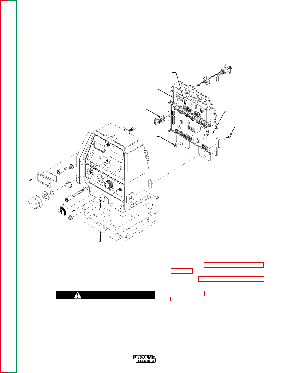
Page 77: F-37, Figure f.8 – case front assembly details
TROUBLESHOOTING & REPAIR
F-37
F-37
MULTI-WELD 350
PERIPHERAL
PC BOARD
JUMPER
PLUG P3
PLUG P31
SCREWS
(7)
WELD
CONTROL
PC BOARD
NUTS
HOT START
ARC FORCE
OTE
CC
SLOPE
PIP
E
ST
IC
K 7
018
GO
UG
E
L11
141
-2
CC
CV
OFF
AM
PS
VO
LTS
A
V
MUL
TI-WELD 350
LINCOLN
ELECTRIC
ELECTR
ODE
INPUT
W
ORK
CHOPPER
TECHNOLOGY
4
4
2
2
0
6
6
10
10
8
8
5
4
3
2
0
6
10
9
8
7
FIGURE F.8 – CASE FRONT ASSEMBLY DETAILS
WELD CONTROL OR PERIPHERAL PC BOARD
REMOVAL AND REPLACEMENT (CONTINUED)
REMOVAL PROCEDURE
Refer to Figure F.8.
1.
Set the CC/CV power switch to OFF.
2.
Remove input power to the machine.
ELECTRIC SHOCK can kill.
Disconnect input power before removing the
case cover and performing tests or making
repairs to the machine.
3.
Perform the Case Cover Assembly
Removal procedure.
4.
Perform the Power Capacitor Discharge
procedure.
5.
Perform the Case Front Assembly
Removal procedure.
6.
Using the 5/16" nut driver, remove the
seven screws from the control box rear
panel.
WARNING