Troubleshooting & repair, Procedure, Capacitor bank removal and replacement (continued) – Lincoln Electric IDEALARC CV-300 User Manual
Page 70
F-31
TROUBLESHOOTING & REPAIR
F-31
IDEALARC CV-300
PROCEDURE
1.
Disconnect main AC input power to
the machine.
2.
Test that the capacitors are dis-
charged using a voltmeter.
a.
Polarity must be observed.
3.
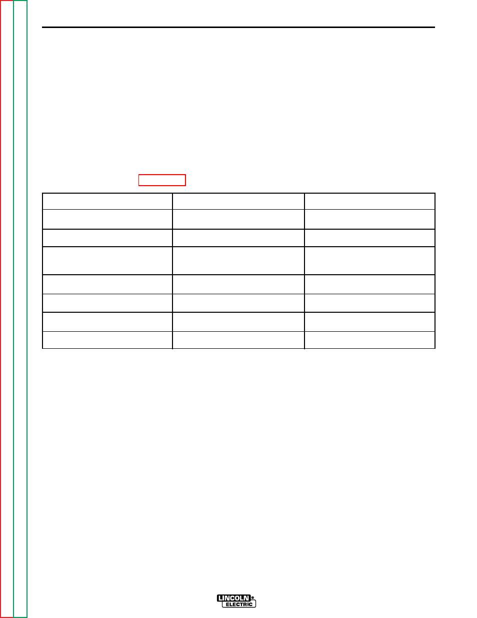
Disconnect the following compo-
nents from the capacitor bank
assembly: See Figure F. 17.
4.
Remove the two screws holding the
capacitor mounting strap to the lift
bail assembly using a 5/16"
Nutdriver.
a.
Note placement of insulation.
5.
Carefully remove the capacitor bank
assembly.
CAPACITOR BANK REMOVAL AND REPLACEMENT (CONTINUED)
PART TO REMOVE
Diode D1 pigtail and lead #224A
Diode D2 pigtail
Diode D3 pigtail, output choke
lead, and leads #224 and #224B
Diode D5 pigtail
Diode D4 pigtail
Positive capacitor jumper strap
Positive capacitor output lead
LOCATION
Negative capacitor bank buss
Negative capacitor bank buss
Negative capacitor bank buss
Negative capacitor bank buss
Positive capacitor jumper strap
Positive capacitor buss
Positive capacitor buss
TYPE WRENCH
1/2" open end wrench
1/2" open end wrench
1/2" open end wrench
1/2" open end wrench
7/16" open end wrench
1/2" open end wrench
1/2" open end wrench