Troubleshooting & repair, Active scr rectifier assembly test (continued) – Lincoln Electric IDEALARC CV-300 User Manual
Page 59
6.
Disconnect the D4 diode pigtail from
the positive strap. See Figure F.14.
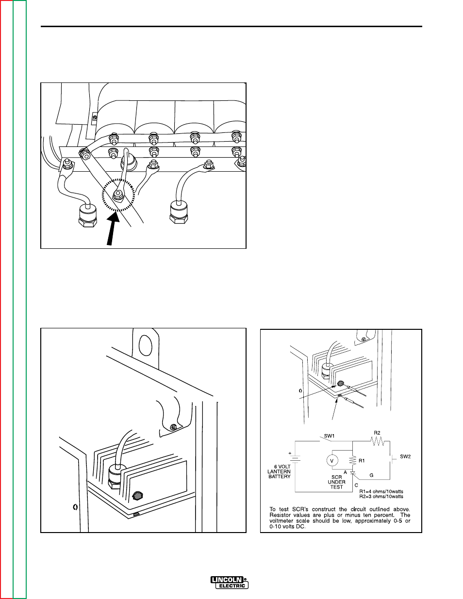
FIGURE F.14 - Procedure to discon-
nect the D4 diode pigtail from the
positive strap.
7.
Remove the red insulating paint
from the heat sink test points. See
Figure F.15.
FIGURE F.15 - Heat sink test points.
NOTE: DO NOT DISASSEMBLE THE
SCR RECTIFIER HEAT SINK ASSEM-
BLY.
8.
Construct the circuit shown in Figure
F.16. One 6-volt lantern battery can
be used. R1 and R2 resistor values
are 010%. Set voltmeter scale low,
at approximately 0-5 volts or 5-10
volts.
a.
Test the voltage level of the bat-
tery. Short leads (A) and (B).
Close switch SW-1. Battery
voltage should be 4.5 volts or
higher. If lower, replace the bat-
tery.
9.
Connect the Tester to the SCR 1 as
shown in Figure F.16.
a.
Connect Tester lead (A) to the
anode.
b.
Connect Tester lead (C) to the
cathode.
c.
Connect Tester lead (G) to the
gate.
FIGURE F.16 - SCR Tester Circuit and
SCR connections.
ACTIVE SCR RECTIFIER ASSEMBLY TEST (CONTINUED)
ANODE
CATHODE
F-20
TROUBLESHOOTING & REPAIR
F-20
IDEALARC CV-300