Theory of operation, Power supply operation (continued), E-2 idealarc cv-300 – Lincoln Electric IDEALARC CV-300 User Manual
Page 35
E-2
THEORY OF OPERATION
E-2
IDEALARC CV-300
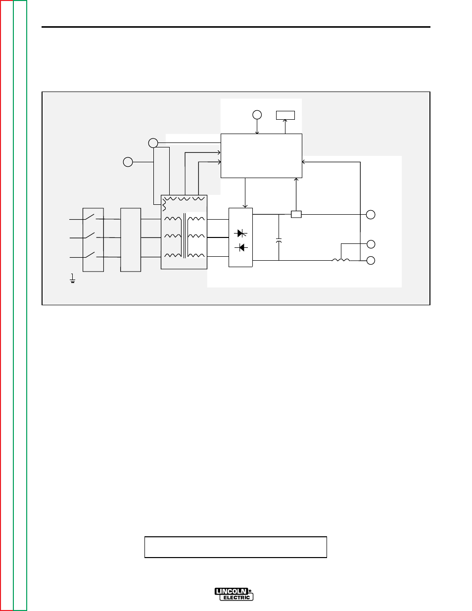
OUTPUT RECTIFICATION, FILTERING,
CONTROL AND FEEDBACK
The main transformer secondary windings are con-
nected to an SCR/Diode hybrid rectifier bridge. This
three phase AC output from the main transformer sec-
ondary is rectified and controlled through the rectifier
bridge. Output current and voltage are sensed at the
shunt and the output terminals and fed back to the con-
trol board. This feedback information is processed in
the control board. The control board compares the
commands of the output control potentiometer (or
remote control) with the feedback information and
sends the appropriate gate firing signals to the rectifier
bridge. The control board also supplies power and sig-
nals to the meter board.
The capacitors and the output choke provide the filter-
ing for the controlled DC output of the CV 300
machine. The choke is tapped for supplying either a
soft (high inductance) or a more harsh (low induc-
tance) welding arc.
Figure E.3 - Output Rectification, Filtering, Control and Feedback
POWER SUPPLY OPERATION (CONTINUED)
INPUT
LINE
SWITCH
MAIN
TRANSFORMER
RECONNECT
PANEL
FAN
MOTOR
OUTPUT
RECTIFIER
+
SHUNT
CHOKE
OUTPUT
TERMINALS
CONTROL BOARD
F
E
E
D
B
A
C
K
G
A
T
E
S
METER
OUTPUT
CONTROL
14 PIN
AMPHENOL
TRIGGER AND REMOTE
12VAC
12VAC
4
2
V
A
C
-
CAPACITORS
+
F
E
E
D
B
A
C
K
-
-
115VAC
NOTE: Unshaded areas of Block Logic
Diagram are the subject of discussion