Theory of operation, Power supply operation, E-1 idealarc cv-300 – Lincoln Electric IDEALARC CV-300 User Manual
Page 34
E-1
THEORY OF OPERATION
E-1
IDEALARC CV-300
INPUT LINE VOLTAGE, LINE SWITCH
AND MAIN TRANSFORMER
The desired three phase input power is connected to
the CV 300 through an input line switch located on the
front of the machine. A reconnect panel allows the user
to configure the machine for the desired input voltage.
This AC input voltage is applied to the primary of the
main transformer.
The main transformer changes the high voltage, low
current input power to a low voltage, high current out-
put. The finishes or "neutrals" of the main secondary
coils are connected together and the three starts of the
secondary windings are connected to the rectifier
assembly. In addition the main transformer also has
several isolated auxiliary windings. The 115 VAC auxil-
iary winding supplies power to operate the cooling fan
and offers up to 5 amps to operate wire feeding equip-
ment. A separate 42 VAC winding is connected to the
14 pin amphenol to supply up to 10 amps for 42 VAC
wire feeders. The two isolated 12 VAC coils supply
power and gate firing timing information to the control
board.
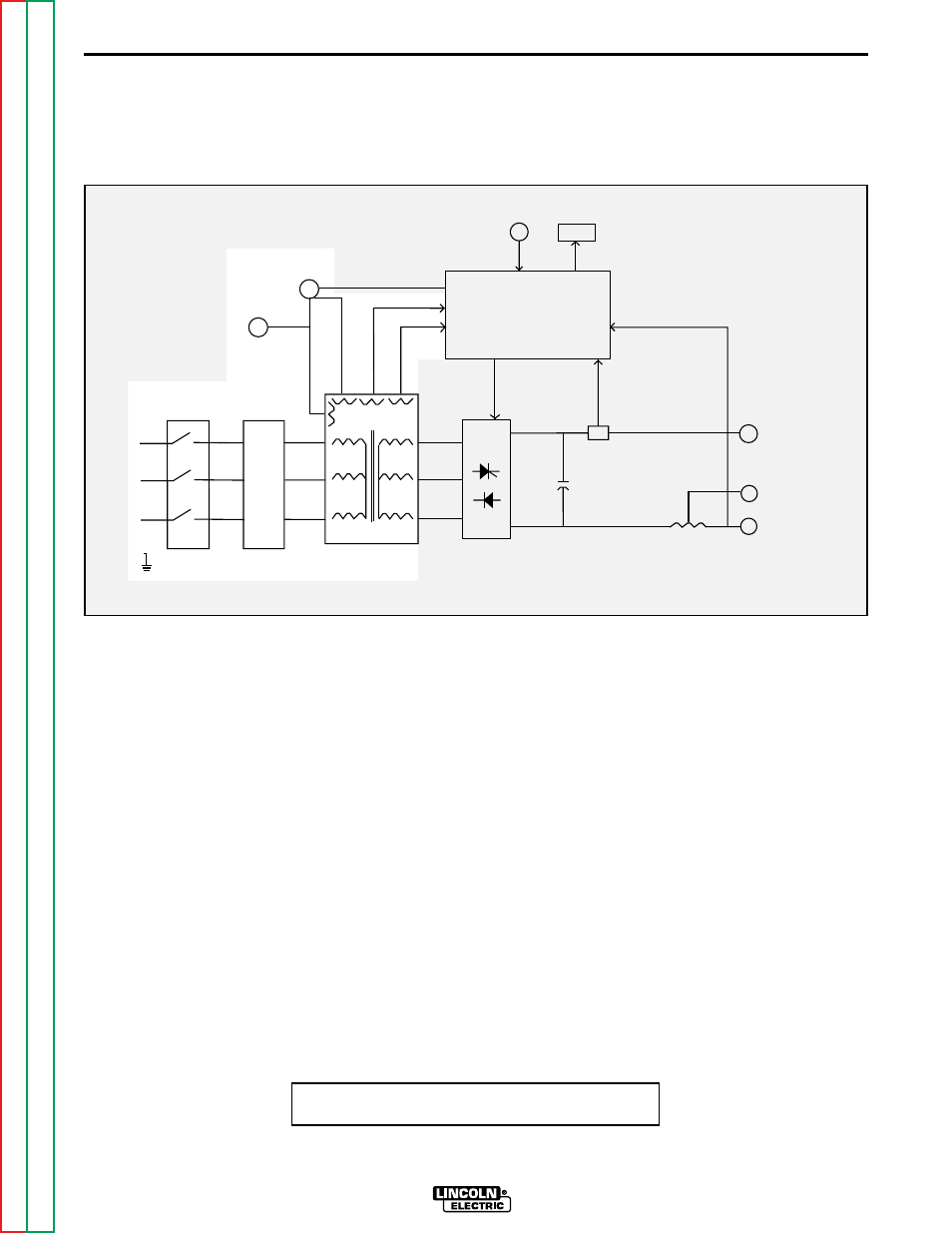
Figure E.2 - Input Line Voltage, Line Switch and Main Transformer
POWER SUPPLY OPERATION
INPUT
LINE
SWITCH
MAIN
TRANSFORMER
RECONNECT
PANEL
FAN
MOTOR
OUTPUT
RECTIFIER
+
SHUNT
CHOKE
OUTPUT
TERMINALS
CONTROL BOARD
F
E
E
D
B
A
C
K
G
A
T
E
S
METER
OUTPUT
CONTROL
14 PIN
AMPHENOL
TRIGGER AND REMOTE
12VAC
12VAC
4
2
V
A
C
-
CAPACITORS
+
F
E
E
D
B
A
C
K
-
-
115VAC
NOTE: Unshaded areas of Block Logic
Diagram are the subject of discussion