For 230/460/575 voltage machines, see figure a.5, Installation – Lincoln Electric IDEALARC CV-300 User Manual
Page 13
A-6
INSTALLATION
IDEALARC CV-300
A-6
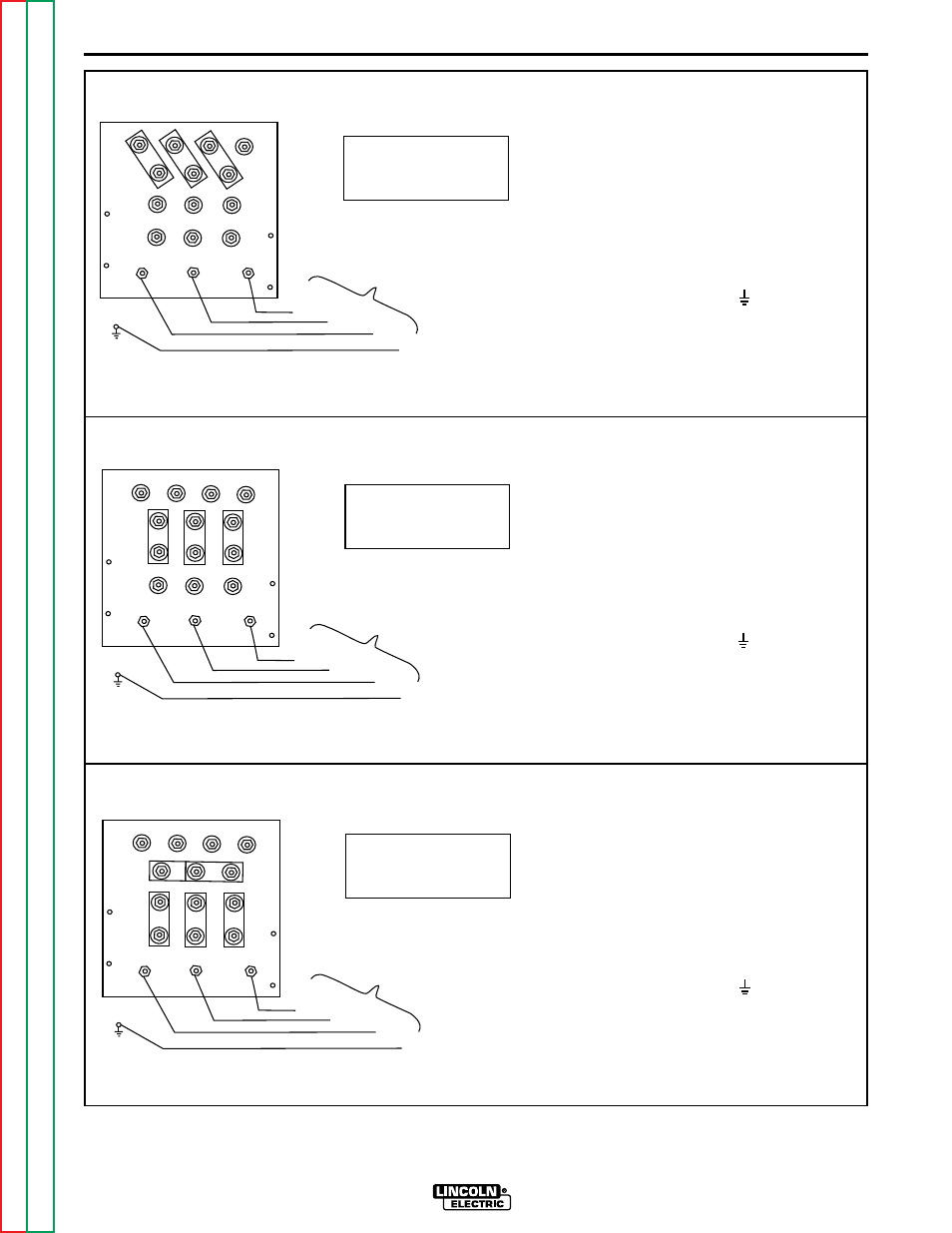
FIGURE A.5 - Reconnect Diagram for 230/460/575 voltage machines.
1.
Check nuts on terminal board for tight-
ness, then place the copper links in the
positions shown. Double up the links in
two of the positions to save them for future
use. Secure the links tightly with the hex
nuts provided. Secure the remaining hex
nuts in place for future use.
2.
Connect L1, L2, & L3 as shown.
3.
Connect terminal marked to ground ter-
minal per National Electrical Code.
1.
Check nuts on terminal board for tight-
ness, then place the copper links in the
positions shown. Secure the links tightly
with the hex nuts provided.
2.
Connect L1, L2, & L3 as shown.
3.
Connect terminal marked to ground ter-
minal per National Electrical Code.
L3
L2
L1
GROUND
INPUT LINES
CONNECTION FOR
575 VOLTS 60HZ.
u
v
w
L3
L2
L1
GROUND
INPUT LINES
CONNECTION FOR
460 VOLTS 60HZ.
u
v
w
L3
L2
L1
GROUND
INPUT LINES
CONNECTION FOR
230 VOLTS 60HZ.
u
v
w