Kenwood TM-V71E User Manual
Page 11
3
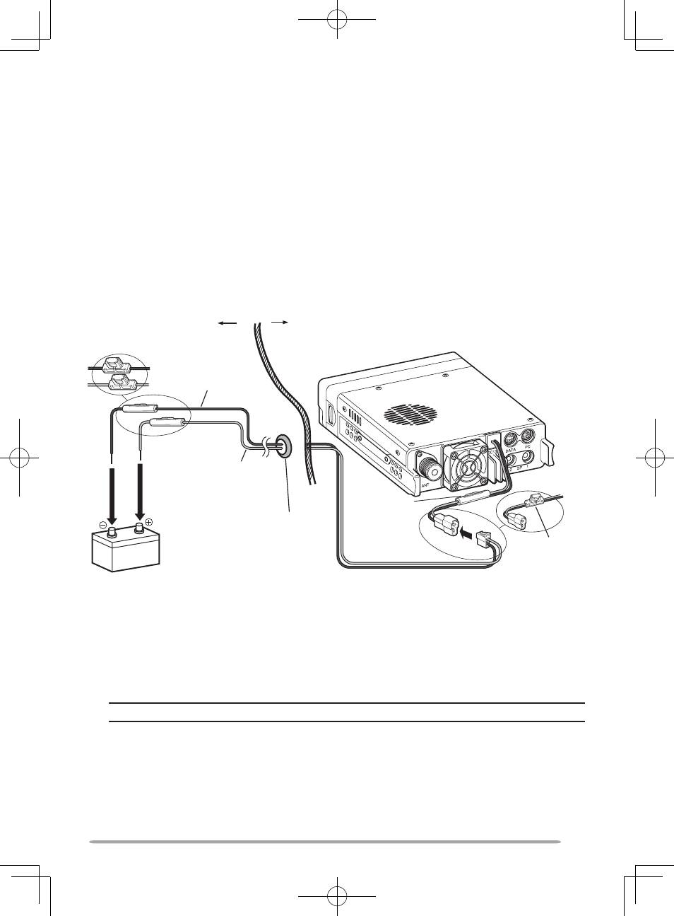
2 After the cable is in place, wind heat-resistant tape around the fuse holder
to protect it from moisture. Tie down the full run of cable.
3 To prevent the risk of short circuits, disconnect other wiring from the
negative (–) battery terminal before connecting the transceiver.
4 Confirm the correct polarity of the connections, then attach the power cable
to the battery terminals; red connects to the positive (+) terminal and black
connects to the negative (–) terminal.
• Use the full length of the cable without cutting off excess, even if the cable is
longer than required. In particular, never remove the fuse holders from the cable.
5 Reconnect any wiring removed from the negative terminal.
6 Connect the DC power cable to the transceiver.
• Press the connectors firmly together until the locking tab clicks.
Passenger compartment
Engine compartment
Black (—) cable
Red (+)
cable
Rubber grommet
Fuse holder (E type)
Fuse holder
(K, M4 types)
Fuse holder
(K, M4 types)
Fuse holder
(E type)
2 V vehicle
battery
DC power cable
n
Fixed Station Operation
In order to use this transceiver for fixed station operation, you will need a
separate 3.8 V DC power supply that must be purchased separately. The
recommended current capacity of the power supply is 3 A.
Note: Do not plug the DC power supply into an AC outlet until you make all connections.
1 Ensure that the transceiver and DC power supply are both OFF.
2 Connect the DC power cable to the regulated DC power supply and ensure
that the polarities are correct (Red: positive, Black: negative).
• Use the supplied DC power cable to connect the transceiver to a regulated
power supply. Do not directly connect the transceiver to an AC outlet.
• Do not substitute the cable with smaller gauge wires.