Kenwood HM-582MD User Manual
Page 6
System connection
6
Preparation section
Basic section
Apprication section
Knowledge section
The system features a free layout with which both the main unit and speakers can be installed either on their
bottom (horizontally, or widthwise) or on their side (vertically, or lengthwise).
CAUTION
&
S
TOP
r
e
c
p
h
o
n
e
s
A
U
X
s
o
u
n
d
s
e
t
m
e
n
u
/
d
e
m
o
d
i s
p
l a
y
CD
^
M
D
^
›
$
TU
N
ER
/BA
N
D
r
e
m
o
t e
disc loading mechanism
Micro hi-fi component system VH-5MD
timer
PUSH
volume/
multi contr
o
l
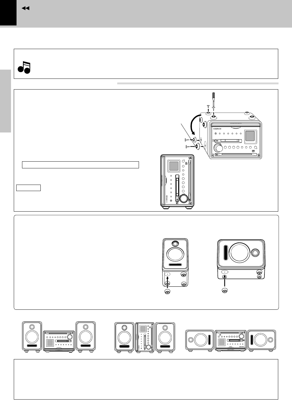
At the factory, the feet have been attached to the
bottom panel for “horizontal” installation.
3 Place the main unit so that the LCD panel comes at
the top as shown in the figure.
CAUTION
Do not install the main unit without feet. Otherwise,
the heat produced inside cannot be well ventilated
and a fire hazard or malfunction may result.
Speakers
The speakers are shipped without feet attached.
Attach the feet by adhesion to the specified posi-
tions according to the desired layout.
Attach the four feet with the following procedure.
Horizontal installation
÷ When you want to change the speaker layout, peel off and
attach the feet again using commercially-available double-
side adhesive tape.
Layout examples
1 Remove the four feet on the front and rear part of
the bottom panel using a screwdriver.
2 Attach the feet to the specified positions on the
side panel.
Installation
÷ When attaching replacement front feet, use only the screws which have been used with the removed feet. (Using other
screws may result in a fire or malfunction.)
÷ Eject the CD, MD and unplug the power cord before installation.
Changing the installation method
View of “vertical” in-
stallation
Notes
Notes
Notes
Main unit
Vertical installation
Vertical installation
Remove the foot from the bottom panel and attach
them onto the side panel.
&
S
TO
P
re
c
p
h
o
n
e
s
A
U
X
s
o
u
n
d
s
e
t
m
e
n
u
/
d
e
m
o
d
is
p
la
y
C
D
^
M
D
^
›
$
TU
N
E
R
/
B
A
N
D
re
m
o
te
di
sc
l
oa
di
ng
m
ec
ha
ni
sm
Mi
cr
o
hi
-f
i
co
mp
on
en
t
sy
st
em
V
H-
5M
D
ti
me
r
PU
SH
volume/
multi control
Feet removed
in step
1
Step
1
Step
2
CAUTION
Be sure to adhere followings. Or proper ventilation will be blocked causing damage or fire hazard.
÷ Do not place any objects impairing heat radiation onto the top of unit.
÷ Leave a space around the unit (from the largest outside dimension including projection) equal or greater than,
shown below.
Top panel : 50 cm Back panel : 10 cm
Use the screws removed in
1 for attaching.
1 Remove dust and dirt from the positions you
want to attach the feet.
2 Peel off the double-side adhesive tape from each
of the provided speaker feet. Attach each feet to
the specified position.