Controls and indicators, Standby mode, Display – Kenwood KRF-V7771D User Manual
Page 14
14
KRF-V7771D (En/T)
Setup
PHONES
INPUT SELECTOR
VOLUME
MPEG
Cinema Re-EQ
DOLBY DIGITAL
CLIP INDICATOR
POWER
ON/STANDBY
A
B
SPEAKERS
MUTE
DOWN
UP
DISPLAY MODE
S VIDEO
V
L-AUDIO-R
CD2 / TAPE2
MONITOR
ON
OFF
AV AUX
2 3
7
5
4
6
@ #
%
$
&
^
9
8
0
1
ST.
ST.
TUNED
TUNED
MUTE
MUTE
!
Standby mode
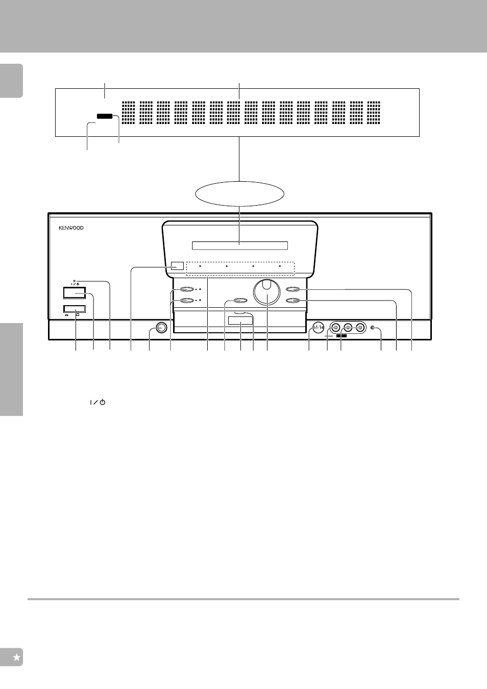
1POWER key
Press to switch the main power ON and OFF.
2ON/STANDBY (
)key
Press to switch the power mode between
STANDBY and ON.
3Standby indicator
Lights in standby mode.
4Remote sensor
Receives signals transmitted from the re-
mote control unit.
5PHONES jack
Use for listening to audio through headphones.
6SPEAKERS keys
Press each key to switch the SPEAKERS A or
SPEAKERS B ON and OFF.
7Indicators
CLIP INDICATOR :
Lights when the input is clipped during
analog to digital signal conversion.
º
DOLBY DIGITAL :
Lights when Dolby Digital is activated.
r
Stereo indicator
MUTE indicator
TUNED indicator
Multi-mode display
While the standby indicator of the unit is lit, a small amount of current is flowing into the unit’s internal circuitry to back up the memory. This
condition is referred to as the standby mode of the unit. While the unit is in the standby mode, it can be turned ON from the remote control unit.
Controls and indicators
Display
MPEG :
Lights when the MPEG is activated.
r
Cinema Re-EQ :
Lights when the Re-EQ is activated.
u
8MUTE key
Press to mute the audio temporarily.
9Remote transmitter
Sends signals to the remote control unit.
0Communication indicator
Lights when signal is input from or output to
the remote control unit.
!VOLUME control knob
Rotate to adjust the volume.
@S VIDEO input jack (AV AUX)
Connect the S VIDEO output jack of an AV
component.
#VIDEO input jack (AV AUX)
Connect the composite video output (RCA)
jack of an AV component.
$AUDIO (L, R) input jacks (AV AUX)
Connect the audio output (RCA) jacks of an AV
component.
%CD2/TAPE2 MONITOR indicator
Lights when the CD2/Tape2 (Monitor) input is
used.
p
^DISPLAY MODE key
Press to switch the display on the receiver.
•
Press for more than 2 seconds to switch the
recording mode.
o
&INPUT SELECTOR key
Press to switch the input as shown below.
TUNER
CD1
MD/Tape1
VIDEO1
VIDEO2
VIDEO3
VIDEO4
AV AUX
PHONO