10 multi-purpose port (mpp) usage, Table 11. mv64462 multi-purpose port assignments, Ee table 11 for the gpio port n – SBE HighWire HW400c/2 User Manual
Page 36
HighWire HW400c/2 User Reference Guide Rev 1.0
3.2.10 Multi-Purpose Port (MPP) Usage
The MV64462 Discovery III includes a 32-bit Multi-Purpose Port (MPP) that can be
used for a variety of possible functions. The HW400c/2 board uses the MPP for the
serial Console Port signals (front-panel RJ-45), REQ and GNT signals for the local
PCI bus, I2C EEPROM activity indicator (used during boot*), and as a detector for
the various on-board interrupt sources.
Interrupts from the PTMC sites, the T8110L, the Ethernet PHYs, the Disk-on-Chip,
and the optional external pushbutton are connected individually to GPIO ports of the
Discovery III, which can then be configured to route them either to the MPC744X, or
to the host through the PCI interrupt output.
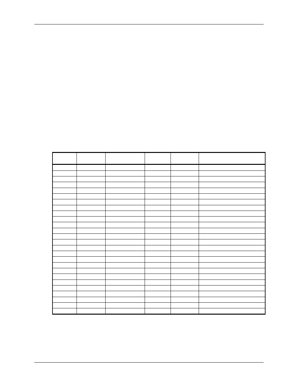
Table 11 lists the MV64462 MPP pin connections on the HW400c/2 board.
Table 11. MV64462 Multi-Purpose Port Assignments
MPP
Pin
Multiplex
Number
Pin Function
In/Out of
Disco III
Active
High/Low Signal Description
MPP0
0x2
S0_TXD
Out
High
Console Port (RJ-45) TXD
MPP1 0x2
S0_RXD
In
High Console Port (RJ-45) RXD
MPP2
0x1
PCI1_GNTn[0]
Out
Low
GNT to PTMC Site A
MPP3
0x1
PCI1_REQn[0]
In
Low
REQ from PTMC Site A
MPP4
0x1
PCI1_GNTn[1]
Out
Low
GNT to PTMC Site B
MPP5
0x1
PCI1_REQn[1]
In
Low
REQ from PTMC Site B
MPP6 0x0
GPIO6
Out
Low Disk-on-Chip
Lock
MPP7
0x4
INITACT
Out
High
I2C EEPROM Active*
MPP14 0x0
GPIO14
In
Low Pushbutton
Interrupt
MPP15
0x0
GPIO15
In
Low
CPU Temp Sensor TCRIT
MPP16
0x4
WD_NMIn
Out
Low
Watchdog Signal to IPMI
MPP17
0x0
GPIO17
In
Low
INTA from PTMC site A
MPP18
0x0
GPIO18
In
Low
INTB from PTMC site A
MPP19
0x0
GPIO19
In
Low
INTC from PTMC site A
MPP20
0x0
GPIO20
In
Low
INTD from PTMC site A
MPP21
0x0
GPIO21
In
Low
INTA from PTMC site B
MPP22
0x0
GPIO22
In
Low
INTB from PTMC site B
MPP23
0x0
GPIO23
In
Low
INTC from PTMC site B
MPP24
0x0
GPIO24
In
Low
INTD from PTMC site B
MPP25
0x0
GPIO25
In
High
T8110L Clock Error
MPP26
0x0
GPIO26
In
High
T8110L System Error
MPP27
0x0
GPIO27
In
Low
PHY A Interrupt
MPP28
0x0
GPIO28
In
Low
PHY B Interrupt
MPP29 0x0
GPIO29
In
Low PHY R Interrupt (RJ-45)
MPP30 0x0
GPIO30
In
Low Disk-on-Chip
Interrupt
MPP31 0x0
GPIO31
In
Low Disk-on-Chip
Busy
Signal
* By default, the HW400c/2 uses the I2C EEPROM during boot. The EEPROM
must contain the appropriate register setting to configure MPP7 as the INITACT
output. This signal is then pulled low after the EEPROM loads to initiate the
processor boot
October 10, 2006
Copyright 2006, SBE, Inc.
Page
24