Figure 6. j8 and j9 with optional reset/nmi cable, Table 7. j8 and j9 pin out, Ble 7) on the – SBE HighWire HW400c/2 User Manual
Page 27
HighWire HW400c/2 User Reference Guide Rev 1.0
Table 7 describes the pin out of J8 and J9. Some of the pins listed are for Factory use
only.
Table 7. J8 and J9 pin out
Header Pin Label
Usage
1
O
N/C. The “o” indicates pin one
2
SCL
TWSI IPMB SCL, for Factory use only
3
none
N/C. Just below the “J8” header title.
4
SDA
TWSI IPMB SDA, for Factory use only
5
NMI
Ground. Used in conjunction with J9, 1, holds
microprocessor Non Maskable Interrupt (NMI) active.
When used with optional reset/NMI cable toggles NMI.
J8
6
(-)
Ground. Used with TWSI cable, for Factory use only
1
O
Non Maskable Interrupt (NMI). The “o” indicates pin
one. Used in conjunction with J8, 5, holds
microprocessor Non Maskable Interrupt (NMI) active.
2 none
N/C
3
none
Reset to the microprocessor. Used in conjunction with
J9, 5, holds microprocessor in reset. When used with
optional reset/NMI cable toggles reset line.
4
I2C2
Select I2C2, Used with J9-6 to select I2C3 mode. For
Factory use only.
5
RST
Ground. In conjunction with J9-3 to hold microprocessor
in reset.
J9
6
I2C2
Ground. Used with J9-4 to select I2C3 mode. For
Factory use only.
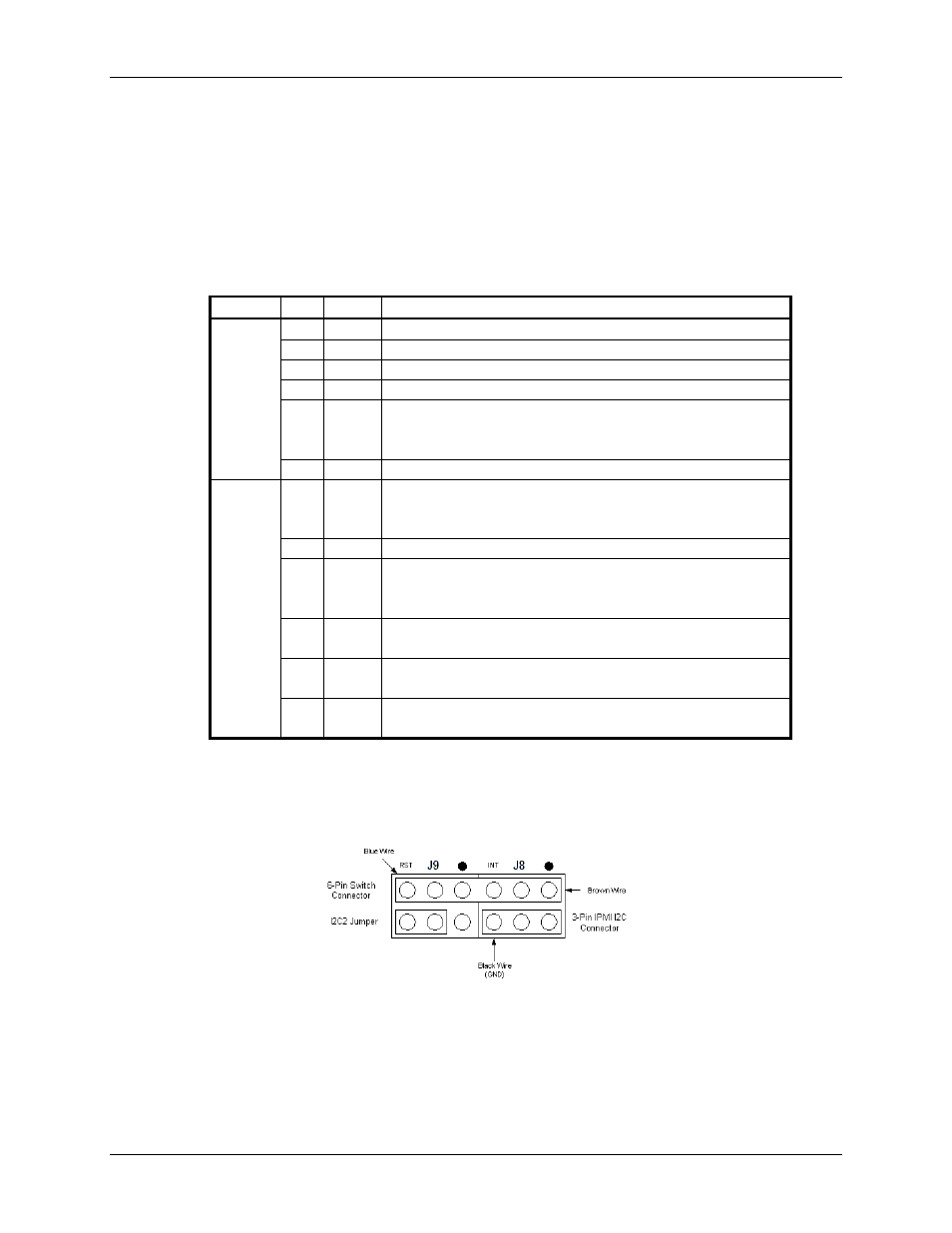
Figure 6. J8 and J9 with optional Reset/NMI cable
Bottom row of J8 and J9 reserved for Factory use only.
October 10, 2006
Copyright 2006, SBE, Inc.
Page
15