Siemens Simatic PC Panel PC 870 User Manual
Page 15
Release 11/02
Unpacking and Installing the Panel PC 670/870
SIMATIC Panel PC 670/870 Start-Up Instructions
1–7
min. 1.5 – max. 6
C
lam
p wi
th gr
u
b
scr
e
w
s
R
z 12
0 (
in
g
ask
et
ar
e
a)
L1
+1
L2
+1
112
±±±±
0.5
L4
±±±±
0.2
L5
±±±±
0.2
112
±±±±
0.5
56
±±±±
1
L3
±±±±
1
S1
±±±±
1
S2
±±±±
1
A1
±±±±
1
A
2
±±±±
1
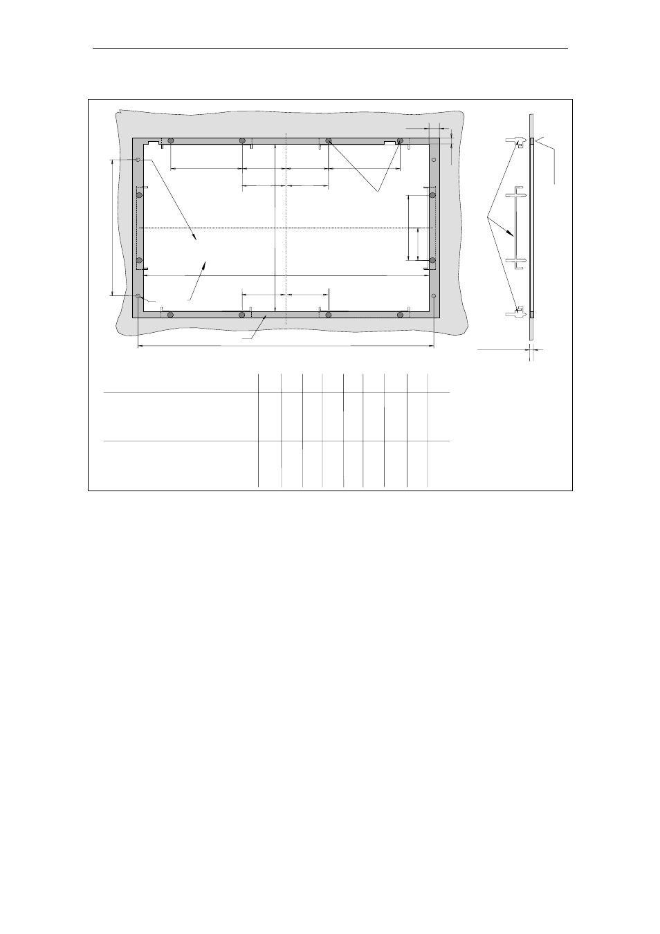
Drill hole for
screw fixings
Gasket area
M6/
∅
∅
∅
∅
7
Pressure points
for clamps
L3
±
1
112
±±±±
0.5
*)
*)
S1
±±±±
1
S1
±±±±
1
*)
cut-outs only for 15" TFT
(8HE)
Operating units
L1 L2 L3 L4 L5 A1 A2 S1 S2
(a) with key-based front panels:
10.4"-TFT / 12.1"-TFT
(b) with touchscreen front panels:
450 290 78 465 235 16 10
–
–
15.1"-TFT
450 321 51 465 279 16 17
–
–
12.1"-TFT
368 290
–
–
–
16 10 35 19
15.1"-TFT
450 290 81 465 235 16 10
–
–
Figure 1–6
Installation cut-out for Panel PC
Refer to Figure 1–6 to check that the screws and pressure points on the rear side,
and the shaded seal area are freely accessible after completion of the installation
cut-out.
Otherwise, it is possible that the installation cut-out cannot be used.
When the conditions mentioned are fulfilled, complete the installation cut-out
according to the next step.