Lan 1/lan 2 ipmi lan (x8st3-f), 8 onboard indicators, Chapter 2: installation – SUPER MICRO Computer X8SIL User Manual
Page 57: A. lan port 1 b. lan port 2 c. ipmi lan, Lan1 lan2, Activity led link led, Jpw1 u2 6, J16 pci1 u2, Jpt1:t pm, Ji2c1/ji2c2
Chapter 2: Installation
2-35
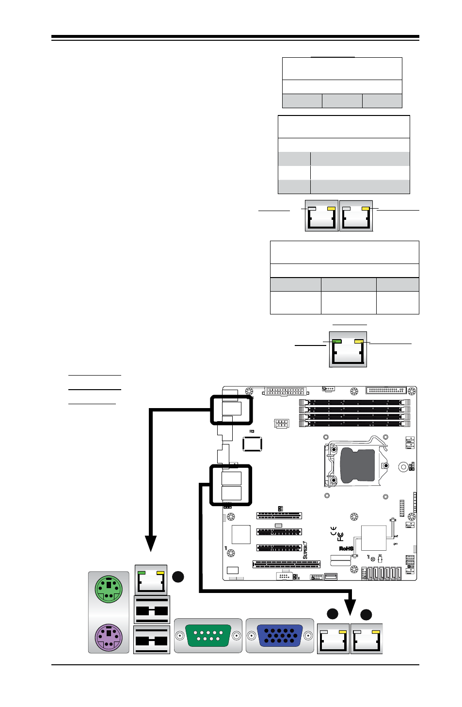
LAN 1/LAN 2 LEDs
Two LAN ports (LAN 1/LAN 2) are located
on the IO Backplane of the motherboard.
Each Ethernet LAN port has two LEDs. The
yellow LED indicates activity, while the Link
LED may be green, amber or off to indicate
the speed of the connections. See the
tables at right for more information.
2-8 Onboard Indicators
A. LAN Port 1
B. LAN Port 2
C. IPMI LAN
LAN 1/LAN 2
Link LEDs (Green/Amber/Off)
LED Color Definition
Off
No Connection or 10 Mbps
Green
100 Mbps
Amber
1 Gbps
LAN 1/LAN 2
Activity LEDs (Yellow)
Color Status Definition
Yellow
Blinking
Active
C
IPMI Dedicated LAN LEDs
In addition to LAN 1/LAN 2, an IPMI Dedi-
cated LAN is also located on the X8SIL/
X8SIL-F. The yellow LED on the right
indicates activity, while the green LED on
the left indicates the speed of the con-
nection. See the tables at right for more
information.
LAN 1/LAN 2
IPMI LAN
(X8ST3-F)
Link LED
Activity LED
IPMI LAN
IPMI LAN Link LED (Left) &
Activity LED (Right)
Color Status Definition
Link (Left)
Green: Solid
100 Mbps
Activity
(Right)
Yellow: Blink-
ing
Active
LAN1 LAN2
Activity LED
Link LED
A
B
MAC CODE
JPI2
C
JF
1
JPW1
U2
6
J8
J6
J5
J1
4
1
J1
3
U6
1
T-SGPIO1
T-
SGPIO2
J24
JLAN2
JLAN1
SPKR
1
JBT1
1
JI2C1
1
JI2C2
1
JL
1
LE4
LE
2
LE3
LE
7
JPT1
1
JP
B
JLED1
1
1
JPUSB1
1
JPL1
1
JPL2
JPG1
JD1
1
FAN2
FAN1
FAN5
1
FAN4
FAN3
J16
PCI1
U2
BAR CODE
1-2:ENABLE
2-3:DISABLE
JPL2:LAN2
JPL1:LAN1
2-3:DISABLE
1-2:ENABLE
JPB:BMC
JPI2C:PWR I2C
JD1:Buzzer/Speaker
COM2
FLOPPY
D
D
R3
1
06
6/
13
33
U
D
IM
M
/R
D
IM
M
re
qu
ire
d
VG
A
CO
M1
USB4
JBT1:CMOS CLEAR
SLOT7 PCI-E X8 GEN2
JPT1:T
PM
JL1
LAN1
JPUSB1:B/P USB WAKE UP
1-2:ENABLE
2-3:DISABLE
DIMM2B
DIMM2A
USB 10/11
JI2C1/JI2C2
USB2/3
SLOT6 PCI-E X8 GEN2
2-3:Disable
1-2:Enable
JAR:
PSU ALARM RS
T
CPU
JLED1:
Po
wer LE
D
OFF:Disable
ON:Enable
2-3:Disable
1-2:Enable
RE
V:
1.00
X8SIL
DESIGNED IN US
A
2-3:DISABL
E
1-2:ENABLE
:CHASSIS INTRUSION
JF
1
ON
LE
D
LED
PW
R
HD
D
NIC1
NIC2
OH/F
F
X
RS
T
PW
R
I-SATA3
I-SATA4
I-SATA2
I-SATA1
I-SATA0
I-SATA5
SLOT5 PCI-E X4 on X8
SLOT4 PCI 33MHZ
KB/MOUSE
DIMM1B
JPG1: VGA
DIMM1A
JAR