Front control panel, X8sil/x8sil-f user's manual, X8sil – SUPER MICRO Computer X8SIL User Manual
Page 44
2-22
X8SIL/X8SIL-F User's Manual
MAC CODE
JPI2
C
JF
1
JPW1
U2
6
J8
J6
J5
J1
4
1
J1
3
U6
1
T-SGPIO1
T-
SGPIO2
J24
JLAN2
JLAN1
SPKR
1
JBT1
1
JI2C1
1
JI2C2
1
JL
1
LE4
LE
2
LE3
LE
7
JPT1
1
JP
B
JLED1
1
1
JPUSB1
1
JPL1
1
JPL2
JPG1
JD1
1
FAN2
FAN1
FAN5
1
FAN4
FAN3
J16
PCI1
U2
BAR CODE
1-2:ENABLE
2-3:DISABLE
JPL2:LAN2
JPL1:LAN1
2-3:DISABLE
1-2:ENABLE
JPB:BMC
JPI2C:PWR I2C
JD1:Buzzer/Speaker
COM2
FLOPPY
D
D
R3
1
06
6/
13
33
U
D
IM
M
/R
D
IM
M
re
qu
ire
d
VG
A
CO
M1
USB4
JBT1:CMOS CLEAR
SLOT7 PCI-E X8 GEN2
JPT1:T
PM
JL1
LAN1
JPUSB1:B/P USB WAKE UP
1-2:ENABLE
2-3:DISABLE
DIMM2B
DIMM2A
USB 10/11
JI2C1/JI2C2
USB2/3
SLOT6 PCI-E X8 GEN2
2-3:Disable
1-2:Enable
JAR:
PSU ALARM RS
T
CPU
JLED1:
Po
wer LE
D
OFF:Disable
ON:Enable
2-3:Disable
1-2:Enable
RE
V:
1.00
X8SIL
DESIGNED IN US
A
2-3:DISABL
E
1-2:ENABLE
:CHASSIS INTRUSION
JF
1
ON
LE
D
LED
PW
R
HD
D
NIC1
NIC2
OH/F
F
X
RS
T
PW
R
I-SATA3
I-SATA4
I-SATA2
I-SATA1
I-SATA0
I-SATA5
SLOT5 PCI-E X4 on X8
SLOT4 PCI 33MHZ
KB/MOUSE
DIMM1B
JPG1: VGA
DIMM1A
JAR
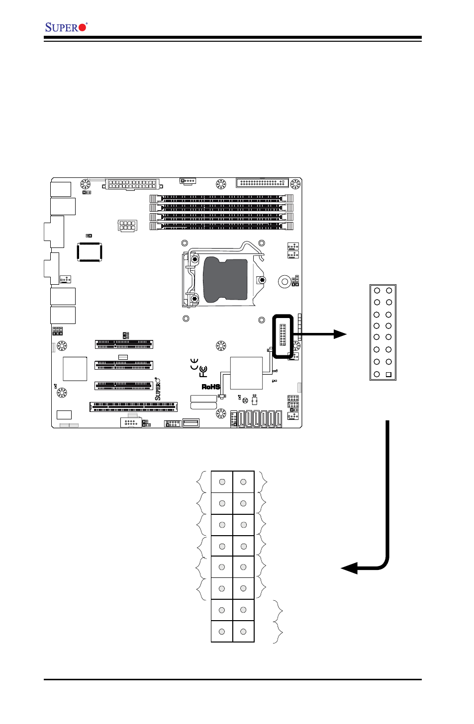
Front Control Panel
JF1 contains header pins for various buttons and indicators that are normally lo-
cated on a control panel at the front of the chassis. These connectors are designed
specifically for use with Supermicro server chassis. See the figure below for the
descriptions of the various control panel buttons and LED indicators. Refer to the
following section for descriptions and pin definitions.
JF1 Header Pins
Power Button
OH/Fan Fail LED
1
NIC1 LED
Reset Button
2
HDD LED
Power LED
Reset
PWR
LED_Anode+
LED_Anode+
LED_Anode+
LED_Anode+
Ground
Ground
X
X
NIC2 LED
LED_Anode+
Pin 15
Pin 16
Pin 1
Pin 2