Chapter 2: installation, Power supply i, C connector power supply (i – SUPER MICRO Computer X8SIL User Manual
Page 51: Ab a. pwr led b. pwr smb, Pwr supply i
Chapter 2: Installation
2-29
A
B
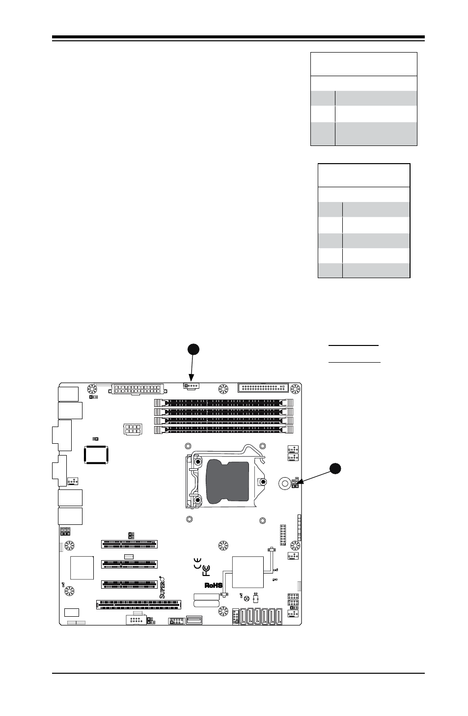
A. PWR LED
B. PWR SMB
Power Supply I
2
C Connector
Power Supply (I
2
C) Connector, locat-
ed at SMB_PS1 on the motherboard.
This connector monitors the status
of the power supply, fan and system
temperature. See the table on the right
for pin definitions.
PWR Supply I
2
C
Pin Definitions
Pin# Definition
1
Clock
2
Data
3
PWR Fail
4
Ground
5
3.3V
Onboard Power LED
An onboard Power LED header is
located at JLED. This Power LED
header is connected to Front Control
Panel located at JF1 to indicate the
status of system power. See the table
on the right for pin definitions.
Onboard PWR LED
Pin Definitions
Pin# Definition
1
VCC
2
No Connection
3
Connection to PWR
LED in JF1
MAC CODE
JPI2
C
JF
1
JPW1
U2
6
J8
J6
J5
J1
4
1
J1
3
U6
1
T-SGPIO1
T-
SGPIO2
J24
JLAN2
JLAN1
SPKR
1
JBT1
1
JI2C1
1
JI2C2
1
JL
1
LE4
LE
2
LE3
LE
7
JPT1
1
JP
B
JLED1
1
1
JPUSB1
1
JPL1
1
JPL2
JPG1
JD1
1
FAN2
FAN1
FAN5
1
FAN4
FAN3
J16
PCI1
U2
BAR CODE
1-2:ENABLE
2-3:DISABLE
JPL2:LAN2
JPL1:LAN1
2-3:DISABLE
1-2:ENABLE
JPB:BMC
JPI2C:PWR I2C
JD1:Buzzer/Speaker
COM2
FLOPPY
D
D
R3
1
06
6/
13
33
U
D
IM
M
/R
D
IM
M
re
qu
ire
d
VG
A
CO
M1
USB4
JBT1:CMOS CLEAR
SLOT7 PCI-E X8 GEN2
JPT1:T
PM
JL1
LAN1
JPUSB1:B/P USB WAKE UP
1-2:ENABLE
2-3:DISABLE
DIMM2B
DIMM2A
USB 10/11
JI2C1/JI2C2
USB2/3
SLOT6 PCI-E X8 GEN2
2-3:Disable
1-2:Enable
JAR:
PSU ALARM RS
T
CPU
JLED1:
Po
wer LE
D
OFF:Disable
ON:Enable
2-3:Disable
1-2:Enable
RE
V:
1.00
X8SIL
DESIGNED IN US
A
2-3:DISABL
E
1-2:ENABLE
:CHASSIS INTRUSION
JF
1
ON
LE
D
LED
PW
R
HD
D
NIC1
NIC2
OH/F
F
X
RS
T
PW
R
I-SATA3
I-SATA4
I-SATA2
I-SATA1
I-SATA0
I-SATA5
SLOT5 PCI-E X4 on X8
SLOT4 PCI 33MHZ
KB/MOUSE
DIMM1B
JPG1: VGA
DIMM1A
JAR