Chapter 1: introduction, Motherboard layout, Jumpers not indicated are for testing only – SUPER MICRO Computer X8SIL User Manual
Page 11: X8sil, Mac code, Bar code
Chapter 1: Introduction
1-3
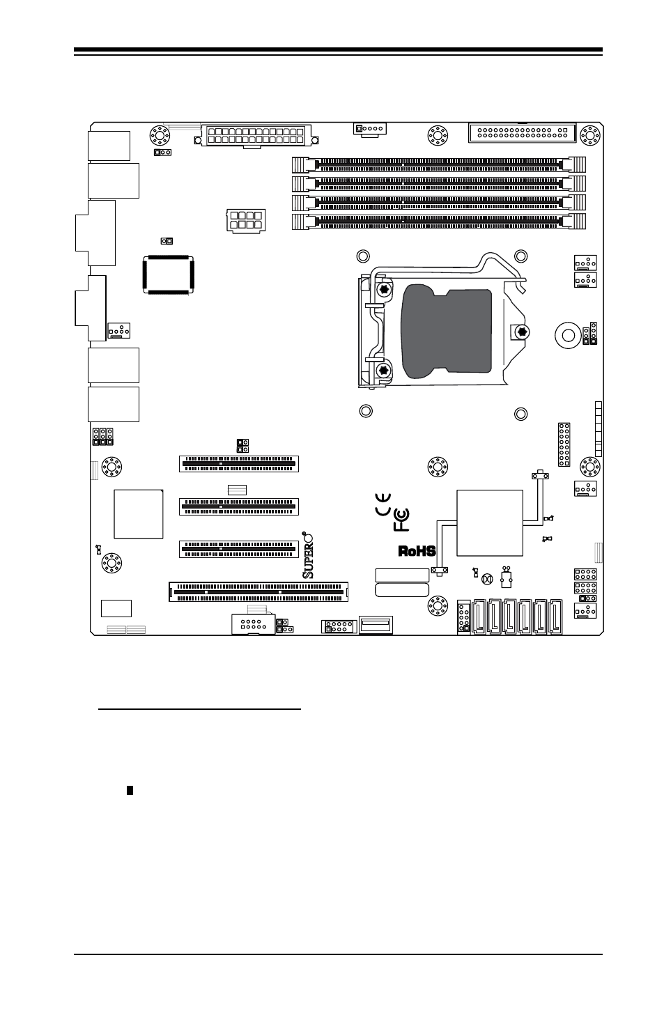
Motherboard Layout
Important Notes to the User
See Chapter 2 for detailed information on jumpers, I/O ports and JF1 front
•
panel connections.
" " indicates the location of "Pin 1".
•
Jumpers not indicated are for testing only.
•
When LE2 (Onboard Power LED Indicator) is on, system power is on. Unplug
•
the power cable before installing or removing any components.
MAC CODE
JPI2
C
JF
1
JPW1
U2
6
J8
J6
J5
J1
4
1
J1
3
U6
1
T-SGPIO1
T-
SGPIO2
J24
JLAN2
JLAN1
SPKR
1
JBT1
1
JI2C1
1
JI2C2
1
JL
1
LE4
LE
2
LE3
LE
7
JPT1
1
JP
B
JLED1
1
1
JPUSB1
1
JPL1
1
JPL2
JPG1
JD1
1
FAN2
FAN1
FAN5
1
FAN4
FAN3
J16
PCI1
U2
BAR CODE
1-2:ENABLE
2-3:DISABLE
JPL2:LAN2
JPL1:LAN1
2-3:DISABLE
1-2:ENABLE
JPB:BMC
JPI2C:PWR I2C
JD1:Buzzer/Speaker
COM2
FLOPPY
D
D
R3
1
06
6/
13
33
U
D
IM
M
/R
D
IM
M
re
qu
ire
d
VG
A
CO
M1
USB4
JBT1:CMOS CLEAR
SLOT7 PCI-E X8 GEN2
JPT1:T
PM
JL1
LAN1
JPUSB1:B/P USB WAKE UP
1-2:ENABLE
2-3:DISABLE
DIMM2B
DIMM2A
USB 10/11
JI2C1/JI2C2
USB2/3
SLOT6 PCI-E X8 GEN2
2-3:Disable
1-2:Enable
JAR:
PSU ALARM RS
T
CPU
JLED1:
Po
wer LE
D
OFF:Disable
ON:Enable
2-3:Disable
1-2:Enable
RE
V:
1.00
X8SIL
DESIGNED IN US
A
2-3:DISABL
E
1-2:ENABLE
:CHASSIS INTRUSION
JF
1
ON
LE
D
LED
PW
R
HD
D
NIC1
NIC2
OH/F
F
X
RS
T
PW
R
I-SATA3
I-SATA4
I-SATA2
I-SATA1
I-SATA0
I-SATA5
SLOT5 PCI-E X4 on X8
SLOT4 PCI 33MHZ
KB/MOUSE
DIMM1B
JPG1: VGA
DIMM1A
JAR