X8sil/x8sil-f user's manual, Aa. bp usb 0/1 wake-up b. bmc jumper, X8sil – SUPER MICRO Computer X8SIL User Manual
Page 56
2-34
X8SIL/X8SIL-F User's Manual
MAC CODE
JPI2
C
JF
1
JPW1
U2
6
J8
J6
J5
J1
4
1
J1
3
U6
1
T-SGPIO1
T-
SGPIO2
J24
JLAN2
JLAN1
SPKR
1
JBT1
1
JI2C1
1
JI2C2
1
JL
1
LE4
LE
2
LE3
LE
7
JPT1
1
JP
B
JLED1
1
1
JPUSB1
1
JPL1
1
JPL2
JPG1
JD1
1
FAN2
FAN1
FAN5
1
FAN4
FAN3
J16
PCI1
U2
BAR CODE
1-2:ENABLE
2-3:DISABLE
JPL2:LAN2
JPL1:LAN1
2-3:DISABLE
1-2:ENABLE
JPB:BMC
JPI2C:PWR I2C
JD1:Buzzer/Speaker
COM2
FLOPPY
D
D
R3
1
06
6/
13
33
U
D
IM
M
/R
D
IM
M
re
qu
ire
d
VG
A
CO
M1
USB4
JBT1:CMOS CLEAR
SLOT7 PCI-E X8 GEN2
JPT1:T
PM
JL1
LAN1
JPUSB1:B/P USB WAKE UP
1-2:ENABLE
2-3:DISABLE
DIMM2B
DIMM2A
USB 10/11
JI2C1/JI2C2
USB2/3
SLOT6 PCI-E X8 GEN2
2-3:Disable
1-2:Enable
JAR:
PSU ALARM RS
T
CPU
JLED1:
Po
wer LE
D
OFF:Disable
ON:Enable
2-3:Disable
1-2:Enable
RE
V:
1.00
X8SIL
DESIGNED IN US
A
2-3:DISABL
E
1-2:ENABLE
:CHASSIS INTRUSION
JF
1
ON
LE
D
LED
PW
R
HD
D
NIC1
NIC2
OH/F
F
X
RS
T
PW
R
I-SATA3
I-SATA4
I-SATA2
I-SATA1
I-SATA0
I-SATA5
SLOT5 PCI-E X4 on X8
SLOT4 PCI 33MHZ
KB/MOUSE
DIMM1B
JPG1: VGA
DIMM1A
JAR
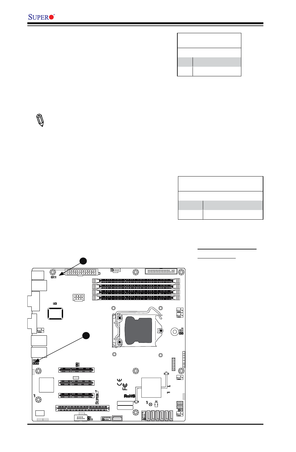
A
A. BP USB 0/1 Wake-up
B. BMC Jumper
USB Wake-Up
Use the JPUSB1 jumper to "wake-up" your
system by pressing a key on a USB keyboard
or clicking the USB mouse. The JPUSB1
jumper is used together with the USB Wake-
Up feature in the BIOS. Enable this jumper
and the USB feature in the BIOS to wake-up
your system via USB devices.
Note: When the USB function is set to
Enabled in the BIOS, and a USB Wake-
up jumper is set to Disabled, remove the
USB devices from the USB ports whose
USB jumper is Disabled before the sys-
tem goes into the standby mode.
JPUSB1 (BackPanel USB
0/1 Wake-up Enable)
Pin# Definition
1-2
Enabled (Default)
2-3
Disabled
B
BMC Jumper
JPB is used to enable or disable the BMC
(Baseboard Management Control) Chip and
the onboard IPMI connection. This jumper is
used together with the IPMI settings in the
BIOS. The default position is on pins 1 and
2 to Enable BMC. See the table on the right
for jumper settings.
BMC IPMI Enable/Disable Jumper
Settings
Settings Definition
Pins 1-2
Enabled (Default)
Pins 2-3
Disabled