Chapter 2: installation, X8sil – SUPER MICRO Computer X8SIL User Manual
Page 49
Chapter 2: Installation
2-27
MAC CODE
JPI2
C
JF
1
JPW1
U2
6
J8
J6
J5
J1
4
1
J1
3
U6
1
T-SGPIO1
T-
SGPIO2
J24
JLAN2
JLAN1
SPKR
1
JBT1
1
JI2C1
1
JI2C2
1
JL
1
LE4
LE
2
LE3
LE
7
JPT1
1
JP
B
JLED1
1
1
JPUSB1
1
JPL1
1
JPL2
JPG1
JD1
1
FAN2
FAN1
FAN5
1
FAN4
FAN3
J16
PCI1
U2
BAR CODE
1-2:ENABLE
2-3:DISABLE
JPL2:LAN2
JPL1:LAN1
2-3:DISABLE
1-2:ENABLE
JPB:BMC
JPI2C:PWR I2C
JD1:Buzzer/Speaker
COM2
FLOPPY
D
D
R3
1
06
6/
13
33
U
D
IM
M
/R
D
IM
M
re
qu
ire
d
VG
A
CO
M1
USB4
JBT1:CMOS CLEAR
SLOT7 PCI-E X8 GEN2
JPT1:T
PM
JL1
LAN1
JPUSB1:B/P USB WAKE UP
1-2:ENABLE
2-3:DISABLE
DIMM2B
DIMM2A
USB 10/11
JI2C1/JI2C2
USB2/3
SLOT6 PCI-E X8 GEN2
2-3:Disable
1-2:Enable
JAR:
PSU ALARM RS
T
CPU
JLED1:
Po
wer LE
D
OFF:Disable
ON:Enable
2-3:Disable
1-2:Enable
RE
V:
1.00
X8SIL
DESIGNED IN US
A
2-3:DISABL
E
1-2:ENABLE
:CHASSIS INTRUSION
JF
1
ON
LE
D
LED
PW
R
HD
D
NIC1
NIC2
OH/F
F
X
RS
T
PW
R
I-SATA3
I-SATA4
I-SATA2
I-SATA1
I-SATA0
I-SATA5
SLOT5 PCI-E X4 on X8
SLOT4 PCI 33MHZ
KB/MOUSE
DIMM1B
JPG1: VGA
DIMM1A
JAR
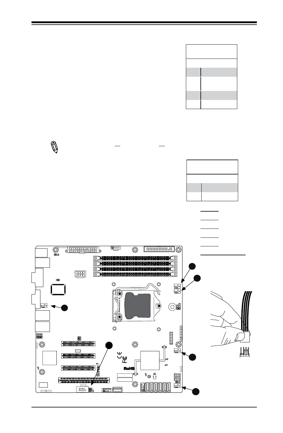
Fan Header
Pin Definitions
Pin# Definition
1
Ground (Black)
2
2.5A/+16V
(Red)
3
Tachometer
4
PWM_Control
Fan Headers
The X8SIL/X8SIL-F has five fan headers (Fan1
~ Fan5). These fans are 4-pin fan headers.
However, Pins 1-3 of the fan headers are
backward compatible with the traditional 3-pin
fans. A fan speed control setting in the BIOS
Hardware Monitoring section allows the BIOS
to automatically set fan speeds based on the
system temperature. The default setting is
Disabled which allows the onboard fans to run
at full speed. Refer to the table on the right for
pin definitions.
A
B
A. Fan1
B. Fan2
C. Fan3
D. Fan4
E. Fan5
F. Chassis Intrusion
C
D
E
F
Chassis Intrusion
A Chassis Intrusion header is located at JL1 on
the motherboard. Attach the appropriate cable
from the chassis to inform you of a chassis intru-
sion when the chassis is opened.
Chassis Intrusion
Pin Definitions (JL1)
Pin# Definition
1
Intrusion Input
2
Ground
Note: Please use all 3-pin fans or all
4-pin fans on a motherboard. Please
do not use 3-pin fans and 4-pin fans
on the same board.