Notice – Woodstock SHOPFOX W1813 User Manual
Page 40
-38-
N(/(*(/Fg\e
J
M
@:<
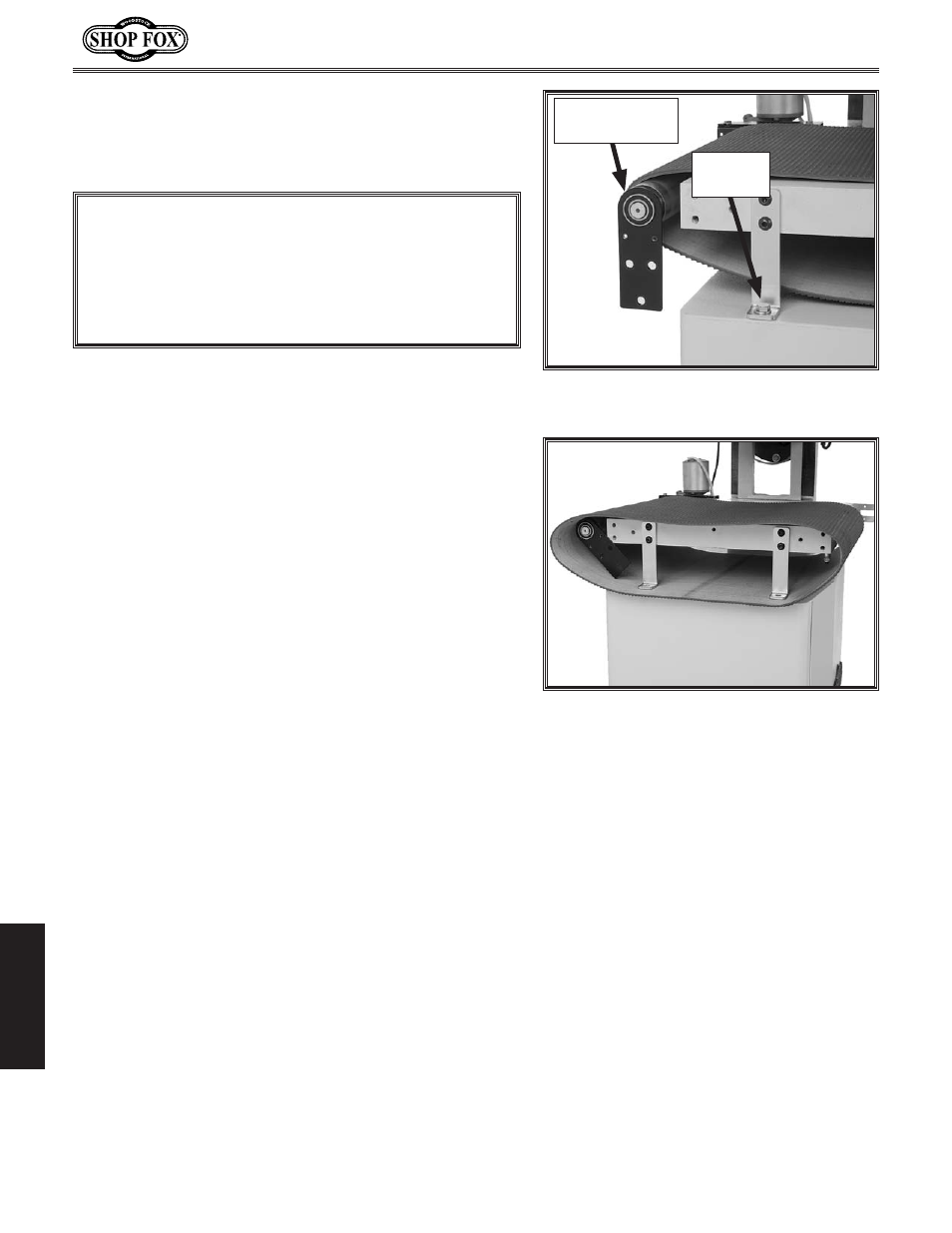
-% Remove the three cap screws securing the left rear
conveyor roller bracket to the conveyor support, but
leave the roller assembly and the bracket in place,
as shown in
=`^li\*/.
.% Loosen, but do not remove, the upper cap screws on
the left side of the conveyor assembly that secure
the sander assembly to the mounting brackets (see
=`^li\*- on GX^\*.).
Efk\1Cffj\e`e^k_\j\ZXgjZi\njn`cci\c`\m\k_\
jkiX`efek_\YiXZb\kj]fik_\e\okjk\g%
/% Remove the two hex bolts and flat washers on the
left side of the conveyor that secure the sander
assembly mounting brackets to the cabinet stand
(see
=`^li\*/).
0% With assistance, lift the left side of the conveyor
assembly up approximately 1", then remove the con-
veyor belt, as shown in
=`^li\*0.
('% Slide the new conveyor belt onto the conveyor
assembly, then re-install the parts removed or loos-
ened in reverse order.
((% Re-tension the conveyor belt, and adjust the track-
ing (refer to
GX^\j)0*').
()% Re-adjust the sanding drum and conveyor parallelism
(refer to
GX^\*)).
=`^li\*0% Removing the conveyor belt
from the machine.
NOTICE
8]k\i cffj\e`e^ k_\ c\]k Zfem\pfi ifcc\i YiXZb\k#
k_\ i\Xi Zfem\pfi ifcc\i Xjj\dYcp `j jlggfik\[ Yp
`kj XkkXZ_d\ek kf k_\ Zfem\pfi dfkfi Xjj\dYcp%
?fn\m\i#kfXmf`[[XdX^`e^k_\ifcc\iXjj\dYcp#;F
EFKglklee\Z\jjXipjkiX`efek_`jXjj\dYcp%
=`^li\*/% Rear conveyor roller bracket
unattached from the conveyor support.
Rear Conveyor
Roller Bracket
Hex Bolt
(1 of 2)