Installation and connections, Basic connections, Dsr-3716 – Sanyo DSR-3709 User Manual
Page 12: Connecting rs-485 terminals
English
11
3
INSTALLATION AND CONNECTIONS
This section describes how to connect the digital video recorder to video cameras and other devices. Be sure to read the
instruction manuals for each connected device.
z
Improper connections can result in malfunction or the
emission of smoke.
z
A separate power supply is required for operation of
each camera.
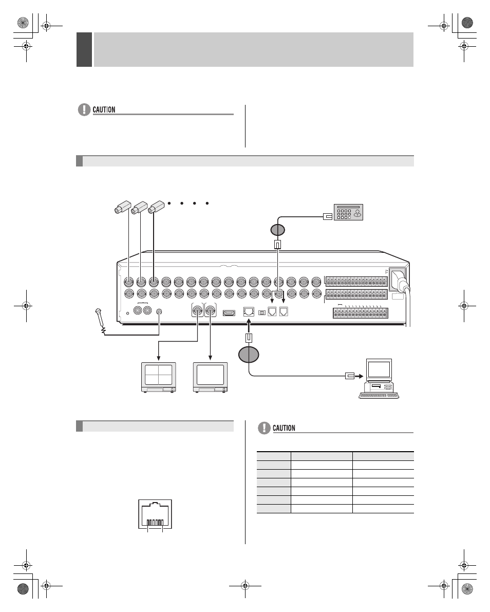
The following diagram shows the connections for cameras, monitors, a microphone, and a PC.
The RS-485 terminals are used to connect a system
controller (sold separately) to the digital video recorder.
After connecting the system controller, you will need to
carry out the settings that are given in the
menu. (JP.96)
Pin locations
z
Do not connect to phone line.
A: Non-inverting driver output/receiver input
B: lnverting driver output/receiver input
Basic connections
USB
LAN
TERMINATE
RS-485
OFF ON
A RS-485 B
ALARM IN
AC IN
SENSOR
ALARM OUT
DO NOT CONNECT TO PHONE LINE
C
CLOC
K IN
CLOC
K OU
T
ALA
RM OUT
ALARM
RESET
ALARM
FULL
NON REC
OUT
WARNING O
UT FULL
SERIES OU
T
EXIT
TIMER
IN
SERIES IN
REMOTE
CONTROL
C 1 2 3 4 5 6 7 8 9 10 11 12 13 14 15 16
C 1 2 3 4 5 6 7 8 9 10 11 12 13 14 15 16
C
R1 R2
1
IN
OUT
ALL
RESET
AUDIO
MONITOR OUT
MON2
MIC IN
IN
OUT
2
3
4
5
6
7
8
9
10
11
12
13
14
15
16
MAIN
02
01
04
03
Video input
terminal
PC
Monitor
(sold separately)
Video input
terminal
Monitor 2
(sold separately)
120 V-240 V AC
(50/60 Hz)
* If the monitor 2 (MON2) is not synchronized
with the connected cameras, vertical
picture instability may occur upon the
switching of camera video.
Camera
(sold separately)
(1-16)
Microphone
(sold separately)
System controller (sold separately)
VSP-8000/9000
The RS-485 connector is
connected to A or B according
to the type of cable.
DSR-3716
The DSR-3709 can be connected to nine cameras.
*1 Wrap the cable once around the
large core clamp to attach it.
*2 Wrap the cable once around the
small core clamp to attach it.
Connecting RS-485 terminals
1
6
Pin number
Connector A signal
Connector B signal
1
Not used
Not used
2
Not used
Not used
3
A
B
4
B
A
5
Not used
Not used
6
Not used
Not used
e05_l8hbg_us_7.fm Page 11 Thursday, November 25, 2004 3:01 PM