Figure 5.3 connector loopback block diagram, 9 configuration signals, Table 5.39 pin names for address bits – SMSC FlexPWR LAN8710i User Manual
Page 52: Configuration signals, Section 5.3.9.1, For information on the address options, Section 5.3.9.1, "physical address bus, Figure 5.3, Smsc, Datasheet
MII/RMII 10/100 Ethernet Transceiver with HP Auto-MDIX and flexPWR
®
Technology in a Small Footprint
Datasheet
Revision 1.0 (04-15-09)
52
SMSC LAN8710/LAN8710i
DATASHEET
5.3.8.3
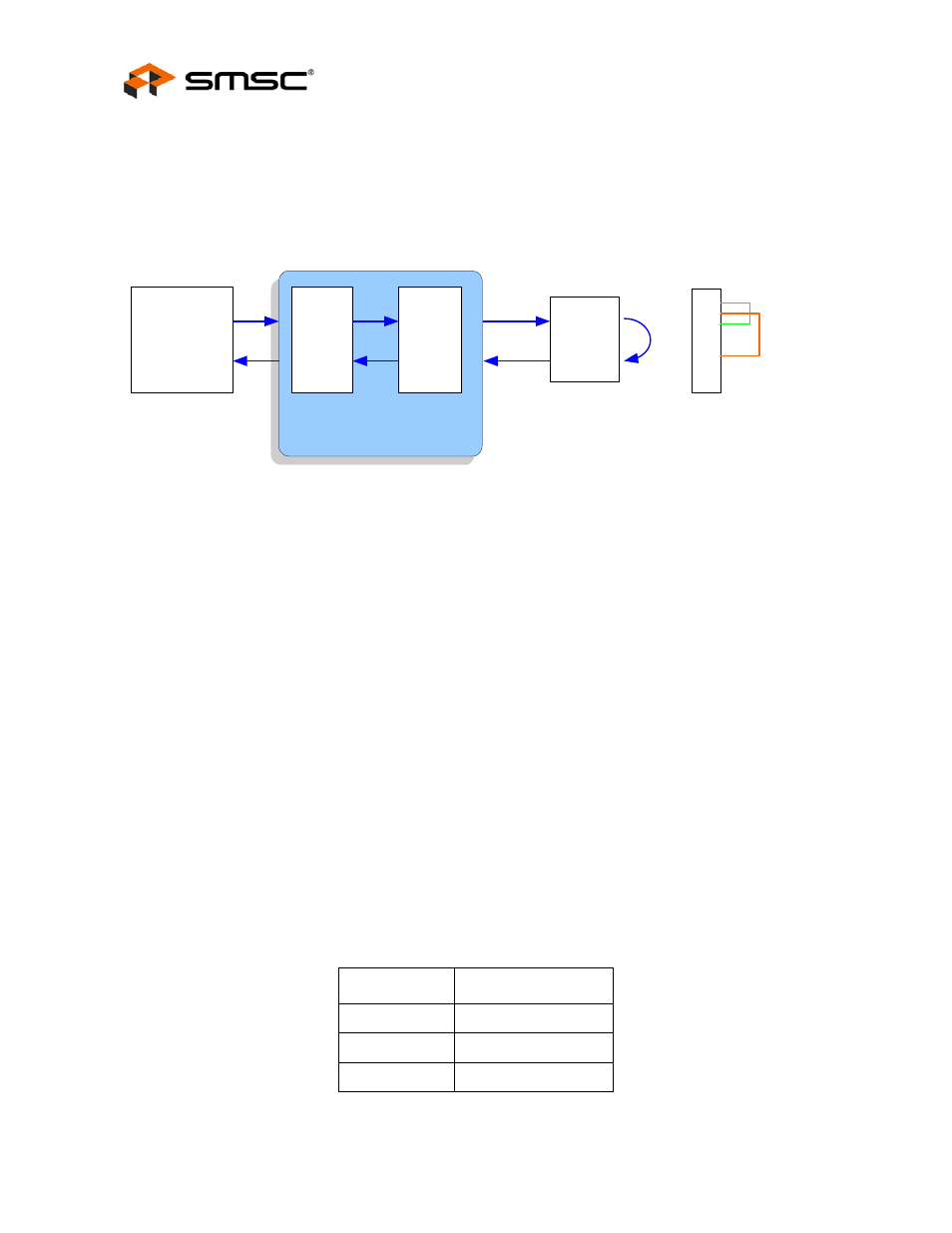
Connector Loopback
The LAN8710/LAN8710i maintains reliable transmission over very short cables, and can be tested in
a connector loopback as shown in
. An RJ45 loopback cable can be used to route the
transmit signals an the output of the transformer back to the receiver inputs, and this loopback will
work at both 10 and 100.
5.3.9
Configuration Signals
The hardware configuration signals are sampled during the power-on sequence to determine the
physical address and operating mode.
5.3.9.1
Physical Address Bus - PHYAD[2:0]
The PHYAD[2:0] bits are driven high or low to give each PHY a unique address. This address is
latched into an internal register at the end of a hardware reset. In a multi-transceiver application (such
as a repeater), the controller is able to manage each transceiver via the unique address. Each
transceiver checks each management data frame for a matching address in the relevant bits. When a
match is recognized, the transceiver responds to that particular frame. The PHY address is also used
to seed the scrambler. In a multi-Transceiver application, this ensures that the scramblers are out of
synchronization and disperses the electromagnetic radiation across the frequency spectrum.
The LAN8710 SMI address may be configured using hardware configuration to any value between 0
and 7. The user can configure the PHY address using Software Configuration if an address greater
than 7 is required. The PHY address can be written (after SMI communication at some address is
established) using the 10/100 Special Modes register (bits18.[4:0]).
The PHYAD[2:0] hardware configuration pins are multiplexed with other signals as shown in
The LAN8710 may be configured to disregard the PHY address in SMI access write by setting the
register bit 17.3 (PHYADBP).
Figure 5.3 Connector Loopback Block Diagram
Table 5.39 Pin Names for Address Bits
ADDRESS BIT
PIN NAME
PHYAD[0]
RXER/PHYAD0
PHYAD[1]
RXCLK/PHYAD1
PHYAD[2]
RXD3/PHYAD2
SMSC
Ethernet Transceiver
10/100
Ethernet
MAC
XFMR
Digital
RXD
TXD
Analog
RX
TX
1
2
3
4
5
6
7
8
RJ45 Loopback Cable.
Created by connecting pin 1 to pin 3
and connecting pin 2 to pin 6.