Read cycle, Write cycle, Datasheet – SMSC FlexPWR LAN8710i User Manual
Page 34
MII/RMII 10/100 Ethernet Transceiver with HP Auto-MDIX and flexPWR
®
Technology in a Small Footprint
Datasheet
Revision 1.0 (04-15-09)
34
SMSC LAN8710/LAN8710i
DATASHEET
applications and in production testing, where the same register can be written in all the transceivers
using a single write transaction.
The MDC signal is an aperiodic clock provided by the station management controller (SMC). The MDIO
signal receives serial data (commands) from the controller SMC, and sends serial data (status) to the
SMC. The minimum time between edges of the MDC is 160 ns. There is no maximum time between
edges.
The minimum cycle time (time between two consecutive rising or two consecutive falling edges) is 400
ns. These modest timing requirements allow this interface to be easily driven by the I/O port of a
microcontroller.
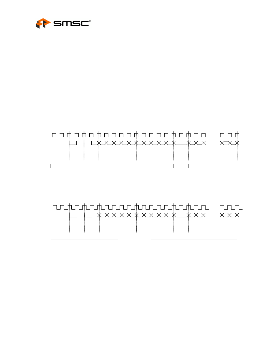
The data on the MDIO line is latched on the rising edge of the MDC. The frame structure and timing
of the data is shown in
and
The timing relationships of the MDIO signals are further described in
Section 6.1, "Serial Management
Interface (SMI) Timing," on page 55
.
Figure 4.7 MDIO Timing and Frame Structure - READ Cycle
Figure 4.8 MDIO Timing and Frame Structure - WRITE Cycle
MDC
MDI0
Read Cycle
...
32 1's
0
1
1
0
A4
A3
A2
A1
A0
R4
R3
R2
R1
R0
D1
...
D15
D14
D0
Preamble
Start of
Frame
OP
Code
PHY Address
Register Address
Turn
Around
Data
Data From Phy
Data To Phy
MDC
MDIO
...
32 1's
0
1
1
0
A4
A3
A2
A1
A0
R4
R3
R2
R1
R0
Write Cycle
D15
D14
D1
D0
...
Data
Preamble
Start of
Frame
OP
Code
PHY Address
Register Address
Turn
Around
Data To Phy