Multiple dust ports, Two machines on same branch line, Calculating duct resistance – Woodstock SHOP FOX W1816 User Manual
Page 33
-31-
W1816 Owner's Manual (Mfg. Since 10/09)
O
PE
R
ATIO
NS
Multiple Dust Ports
If your machine has multiple dust ports, add the total CFM
given for each dust port size from
Figure 40. Refer to
the chart in
Figure 45 and find the CFM that is closest to
your total to determine the correct branch size. Split the
branch line just before the dust ports with matching duct
sizes.
Two Machines on Same Branch Line
If both machines will be running at the same time,
add the total CFM given for each dust port size from
Figure 40.
If both the machines will never be run at the same time,
reference the machine with biggest dust port to
Figure
45 and add blast gates after the Y-branch to open/close
the line to each machine.
Calculating Duct Resistance
Adding duct work, elbows, branches and any other
components to a duct line increases airflow resistance
(static pressure loss). This resistance can be minimized by
using rigid (smooth) pipe and gradual curves, as opposed
to flexible pipe and 90˚ elbows.
To help you think about this resistance, imagine riding a
bicycle in a tunnel that is an exact replica of your duct
work. If the inside of the tunnel is very bumpy (flexible
pipe) and has a lot of sharp turns (90˚ elbows), it will take
a lot more effort to travel from one end to the other.
The purpose of calculating the resistance is to determine
if it is low enough from the machine to the dust collector
to meet the given CFM requirement for the machine. Use
the charts in
Figure 46 to calculate the resistance of duct
work.
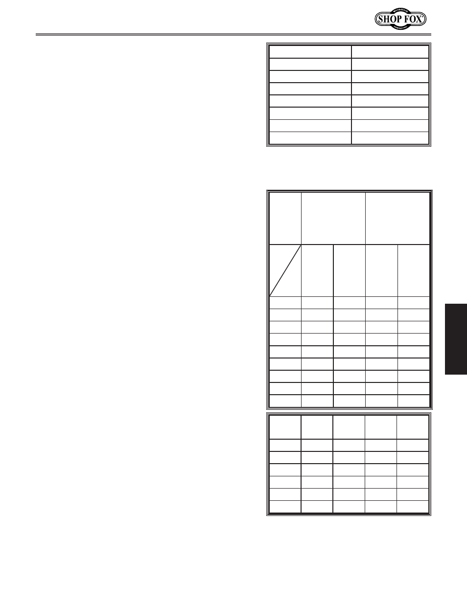
Total CFM
Branch Line Size
600
5"
700
5"
800
6"
1000
6"
1200
7"
1400
8"
1600
8"
Figure 45. Branch line sizing chart by
total CFM (for use when multiple machines
share the line).
Duct
Dia.
Approximate
Static
Pressure Loss
Per Foot of
Rigid Pipe
Approximate
Static
Pressure Loss
Per Foot of
Flex Pipe
Main
Lines
@
3500
FPM
Branch
Lines
@
4000
FPM
Main
Lines
@
3500
FPM
Branch
Lines
@
4000
FPM
2"
.091
.122
.35
.453
2.5"
.08
.107
.306
.397
3"
.071
.094
.271
.352
4"
.057
.075
.215
.28
5"
.046
.059
.172
.225
6"
.037
.047
.136
.18
7"
.029
.036
.106
.141
8"
.023
.027
.08
.108
9"
.017
.019
.057
.079
Fitting
Dia.
90˚
Elbow
45˚
Elbow
45˚
Y
90
Y
3"
.47
.235
.282
.188
4"
.45
.225
.375
.225
5"
.531
.266
.354
.236
6"
.564
.282
.329
.235
7"
.468
.234
.324
.216
8"
.405
.203
.297
.189
Figure 46. Airflow resistance (static
pressure loss) charts.