Star Trac E-TRi User Manual
Page 14
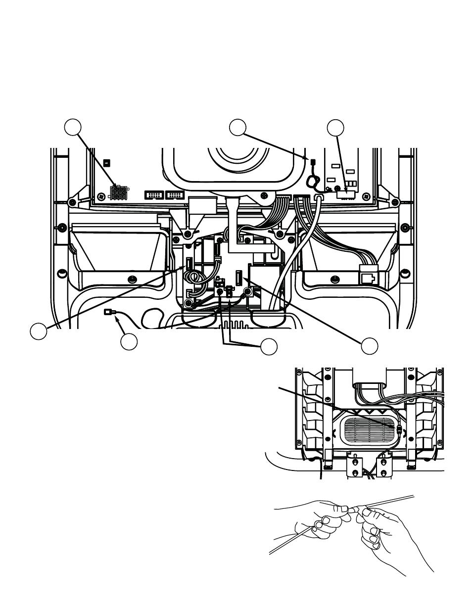
With the changes now completed on the display, it is now time to re-install the display to the base unit.
There are the (3) cables from the PVS mount that will need to be attached to the display. One cable
from the PVS mount will be fed through the display which will be connected to the head phone jack
later. The fifth cable from the PVS mount, which is the coax, will be connected to the coax on the base
unit. There are (2) cables from the base unit that will be connected to the display. Use the image
below to help reference the needed points on the display.
S
TEP
14
Take the coax cable from the PVS mount and
attach it to the coax cable on the base unit.
Tighten the connectors snug to each other.
S
TEP
15
Take the 5” piece of tape from the PVS kit and
wrap the connectors so that all of the metal surface
is covered.
14
STAR TRAC P
ERSONAL
V
IEWING
S
CREEN
O
WNER
’
S
G
UIDE
12 Pin
Connector
Heart Rate
Connector
(2) DC Power
Connectors
RCA Connector
PVS Remote
Connector
Heart Rate Ground
Connector
Coax
Cable
1
2
3
4
7
6
5
Center Console
Ground Connector