Star Micronics RS232 User Manual
Page 22
– 18 –
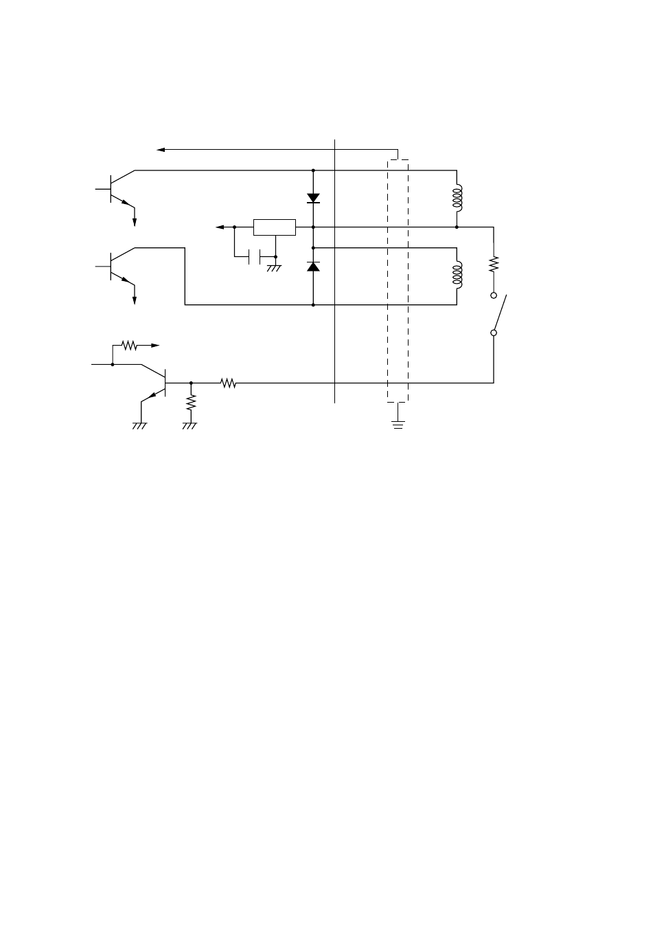
■ Drive circuit
The recommended drive circuit is shown.
NOTES:
1. Peripheral units #1 and #2 cannot be driven simultaneously.
When driving a device continuously, do not use drive duty above 20%.
2. Compulsion switch status is available as status data.
3. Resistance for coils L1 and L2 is not less than 24 ohms.
4. Absolute maximum ratings for diodes D1 and D2 (at Ta=25˚C):
Average rectified current Io = 1A
Maximum forward surge current (60Hz,1-cycle sine wave) I
FSM
=40A
5. Absolute maximum rating for transistors TR1 and TR2 (at Ta = 25˚C):
Collector current Ic = 2A
7824
F.G
TR1
M-GND
TR2
M-GND
TR3
+5V
+24V
R1
R2
6
5
4
3
2
1
L1
L2
R3
4.7k
Ω
1/4W
Frame
ground
D1
D2
Peripheral
unit 1
With shield
Peripheral
unit 2
Compulsion
switch
[Drive output 24V, max. 1.0 A]
See also other documents in the category Star Micronics Printers:
- LC-90 (131 pages)
- LC-240C (82 pages)
- MP500 Series (2 pages)
- Star SP317 (63 pages)
- SP200F (111 pages)
- NL-10 (35 pages)
- MP115MP-24G-A (42 pages)
- LC-6211 (60 pages)
- 800C (76 pages)
- SLIP SP298 (79 pages)
- LC-1021 (91 pages)
- SP200F SERIES (90 pages)
- SP200F SERIES (114 pages)
- 150 (151 pages)
- LC-1011C (88 pages)
- FUTUREPRINT TSP100 (32 pages)
- SP700 Series (2 pages)
- DP8340RC (40 pages)
- SP342F-A (62 pages)
- PR921-24-A (31 pages)
- SP312F (36 pages)
- SP300 Series (70 pages)
- SP317 (63 pages)
- SP2000 Series (147 pages)
- LC-8021 (86 pages)
- NP-325 (45 pages)
- DP8340 (59 pages)
- PW2000-24 (4 pages)
- HL 80825321 (176 pages)
- Line Thermal Printer (181 pages)
- PUNKT-MATRIX-DRUCKER LC-7211 (182 pages)
- Automatic Sheet Feeder SF-15HA (42 pages)
- Star futurePRNT TSP100GT (2 pages)
- Star SP200 Series (127 pages)
- PT-10Q (36 pages)
- SP298 Series (144 pages)
- LC-8521 (116 pages)
- RSR 28 (5 pages)
- SP320S (94 pages)
- Dot Impact Printer (104 pages)
- LC-4521 (191 pages)
- PT-10Y (32 pages)
- Line Thermal/Dot Printer (209 pages)
- ATAR LC-500 (72 pages)