Star Micronics RS232 User Manual
Page 19
– 15 –
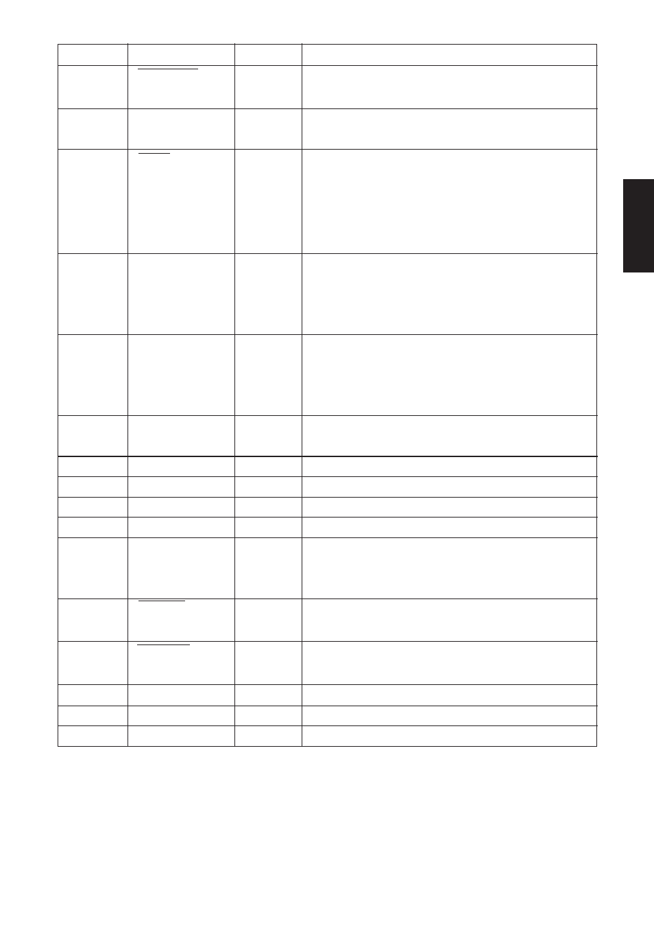
Pin no
Signal name
Direction
Function
1
STROBE
IN
Strobe pulse for data read. Usually HIGH;
goes LOW to trigger data read.
2-9
DATA 1~8
IN
Parallel data lines for eight-bit data. HIGH
is “1”; LOW is “0”.
10
ACK
OUT
Printer outputs this pulse for approxi-
mately 9
µ
s to indicate that data read is
completed. Printer becomes ready to
receive new data at the moment the ACK
pulse ends.
11
BUSY
OUT
DC-level signal indicating printer’s cur-
rent status. LOW indicates that printer is
ready to receive the next data; HIGH
indicates that printer is unable to receive.
12
PAPER OUT
OUT
DC-level signal indicating whether printer
has paper. The signal stays LOW while paper
is present; it goes HIGH to indicate that paper
has run out.
13
SELECTED
OUT
DC-level signal; stays HIGH while printer is
online.
14-15
N/C
Not used
16
SIGNAL GND
Signal ground
17
CHASSIS GND
Printer-frame ground
18
+5V
Outputs +5V (Max. 50mA)
19-30
TWISTED
Return pins for various signals. Each pin is
connected to the corresponding signal line by
twisted pair line.
31
RESET
IN
LOW level causes printer to reset its control
circuitry and return to its initial state.
32
ERROR
OUT
Goes LOW to indicate that printer is unable to
print.
33
EXT GND
Ground terminal for external connection
34-35
N/C
Not used
36
–
–
Fixed “HIGH” at printer side
PARALLEL
PAIR RETURN