5. data protocol, 5-1. dtr mode – Star Micronics RS232 User Manual
Page 14
– 10 –
4-5. Data Protocol
4-5-1. DTR mode
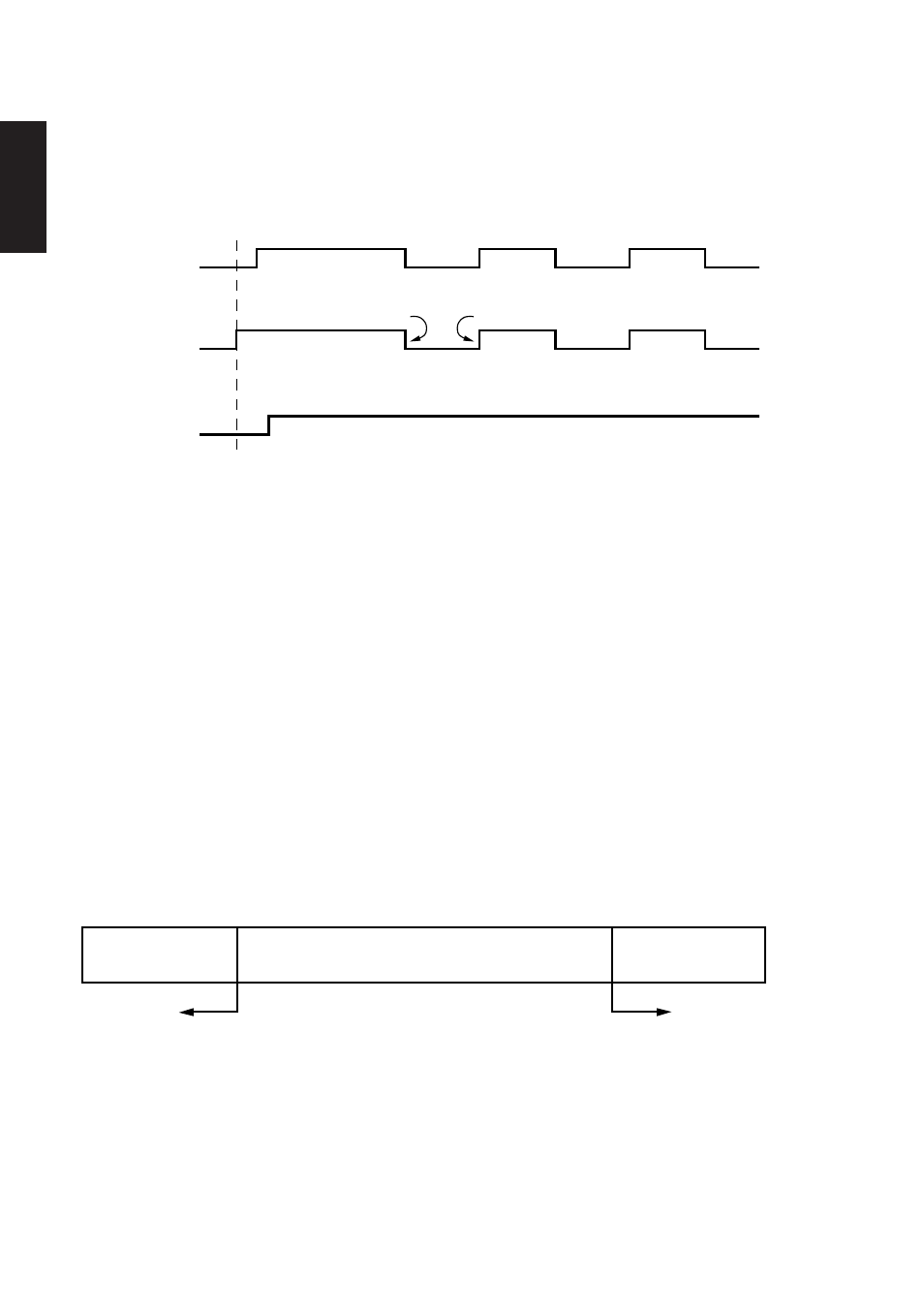
This mode is accessed when the DIP switch 1-6 is set to ON.
Signals are controlled using the DTR line as a BUSY flag.
Immediately after power on (provided that no error occurs), the printer sets DTR
to “SPACE” to indicate that it is ready to receive data. When the host detects that
DTR is in “SPACE” condition, it begins sending text data over the RXD line.
When the printer’s remaining buffer space falls to *256 bytes or less, the printer
sets DTR to “MARK.” The host responds by halting the data transfer. However,
note that the printer remains capable of receiving data until the buffer becomes
full.
Available buffer space increases as the printer prints the buffered data. When the
printer has cleared all but the last *256 bytes of data, it sets DTR back to “SPACE”
to indicate that it is ready to receive more data.
* 16 bytes when the buffer size is set to 45 bytes
RXD
DTR
Data
Data Data
Buffer full
Buffer empty
Printing
Power ON
SERIAL
Data buffer full
Nearly full
Nearly empty
Empty
DTR
“MARK”
DTR
“SPACE”
*256 bytes
remaining
*256 bytes