Power – JVC DLA-M4000LU User Manual
Page 11
No.51666
DLA-M4000LU
DLA-M4000LE
20
Connecting to Various Devices (Cont.)
Examples of System Configuration
Before connection, be sure to turn off both the projector and the equipment to be connected.
• Also, read the manuals which came with the equipment.
R
RGB
Y/C
VIDEO
G
H/CS
B
V
PR/R-Y
PB/B-Y
Y
RGB OUT
RS-232C
REMOTE
RGB IN-2
CONTROL
EXT. IN
RGB IN-1
R
RGB
Y/C
VIDEO
G
H/CS
B
V
PR/R-Y
PB/B-Y
Y
RGB OUT
RS-232C
REMOTE
RGB IN-2
CONTROL
EXT. IN
RGB IN-1
Example of a basic system
• By connecting an RGB switcher, a variety of input sources can be input to the projector as RGB signals. Using the
remote control supplied, you can select the channel for an input source and project an image optimal to the source.
HDTV 2
Computer 1
RGB switcher
Computer 2
Projector
HDTV 1
HDTV 2
Computer 1
Dedicated switcher
(sold separately)
Computer 2
Projector
HDTV 1
Control cable
Signal cable
Example of a dedicated switcher system
• When used in combination with a dedicated switcher, the projector has its channels automatically switched in unison
as the input to the switcher is changed.
For information on dedicated switchers, consult the dealer who performed the installation and adjustments or a local
service center.
Notes
Video image displayed on devices whose image signal is unstable, such as a video deck, may be disturbed. (This can occur when the
projectors is not yet adjusted at the time of installation, or when a new device is added.)
In such a case, ask the dealer where you purchased the projector or a local service center to adjust the projector.
It is recommended that you use a video deck that is equipped with an image signal correction function (such as time base corrector or frame
synchronizer).
21
POWER
R
RGB
Y/C
G
H/C
S
B
V
RGB OUT
RS-232C
REMOTE
RGB IN-2
EXT. IN
RGB IN-1
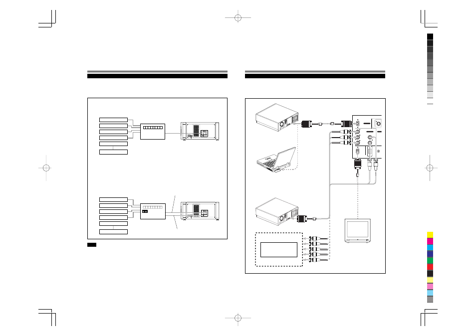
Connecting to Various Devices (Cont.)
Connecting to Computer Devices
Before connection, be sure to turn off both the projector and computer devices.
• Read the manual which comes with each device thoroughly.
• Use the separately available computer connection cable. Also, prepare cables required for connecting the devices connected.
• Desktop type
• Note type
• Desktop type
To monitor connector
* There are some note types which do not allow the
computer’s LCD to work if an external display is connected.
With such a note type, the LCD display and external display
output need to be switched.
To monitor connector
• RGB output devices
Laser video disc player, etc.
Computer cable
(separately available)
T
o
RGB IN-2
Separate cable
(separately available)
To RGB IN-1
T
o
RGB OUT
To
V
T
o
H/Cs
Cable supplied with the
display (or separately
available)(D-sub 3-row
15-pin)
Display monitor
* When a monitor is connected to the
COMPUTER OUT terminal, you can view
the video from the computer on the
monitor.
To R
To G
To B
To V
To H/Cs
To R
To G
To B