Figure 72: ethernet cable connector, A console server – Juniper Networks EX8208 User Manual
Page 208
Ensure that you have an Ethernet cable with an RJ-45 connector available. An RJ-45
cable and an RJ-45 to DB-9 serial port adapter are supplied with the switch.
Figure 72 on page 182 shows the RJ-45 connector of the Ethernet cable supplied with the
switch.
Figure 72: Ethernet Cable Connector
NOTE: If your laptop or PC does not have a DB-9 male connector pin and you want to
connect your laptop or PC directly to an EX Series switch, use a combination of the
RJ-45 to DB-9 female adapter supplied with the switch and a USB to DB-9 male adapter.
You must provide the USB to DB-9 male adapter.
To connect an EX Series switch to a management console (see Figure 73 on page 182 and
Figure 74 on page 183):
1.
Connect one end of the Ethernet cable into the console port (labeled
CON
or
CONSOLE
) on the EX Series switch.
For the location of the
CON/CONSOLE
port on different EX Series switches:
•
See Rear Panel of an EX2200 Switch.
•
See Rear Panel of an EX3200 Switch.
•
See Rear Panel of an EX4200 Switch.
•
See Front Panel of an EX4500 Switch.
•
See “Switch Fabric and Routing Engine (SRE) Module in an EX8208 Switch” on
page 24.
•
See Routing Engine (RE) Module in an EX8216 Switch.
2.
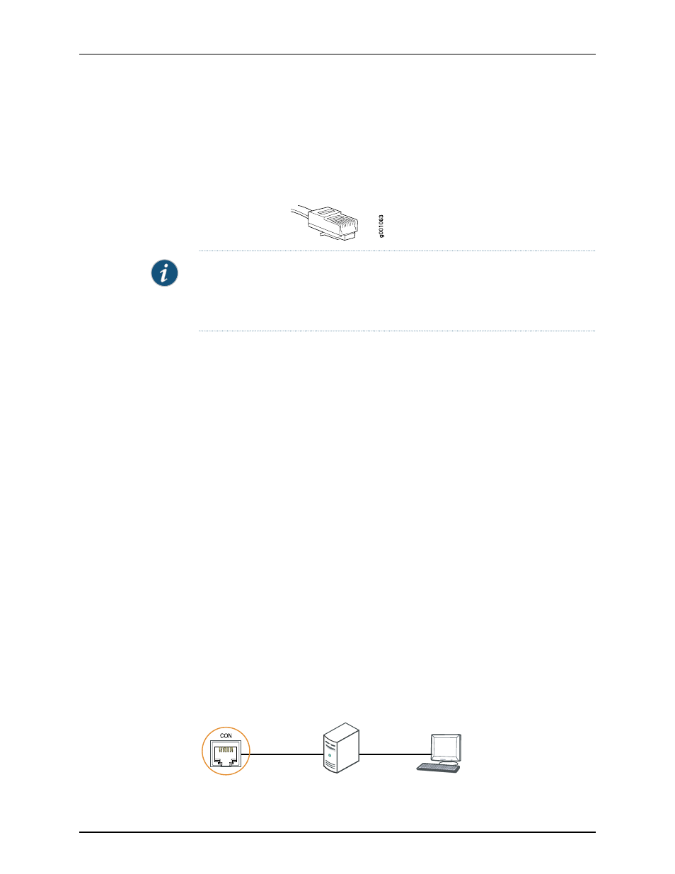
Connect the other end of the Ethernet cable into the console server (see Figure 73
on page 182) or management console (see Figure 74 on page 183).
To configure the switch from the management console, see“Connecting and Configuring
an EX Series Switch (CLI Procedure)” on page 190 or “Connecting and Configuring an EX
Series Switch (J-Web Procedure)” on page 192.
Figure 73: Connecting an EX Series Switch to a Management Console
Through a Console Server
g020547
Console server
PC
To Console port
(on the switch)
Copyright © 2010, Juniper Networks, Inc.
182
Complete Hardware Guide for EX8208 Ethernet Switches