Connecting to editing sytem, Connection – JVC BR-DV6000U User Manual
Page 20
32
VIDEO
LINE
IN
OUT
MONITOR
OUT
DC12V
DV
IN/OUT
IN
OUT
OFF
AUDIO
REMOTE2
IN
B-Y
R-Y
SYNC IN
TIME CODE
IN
OUT
Y
COMPONENT
OUT
CH 1/3
CH 2/4
IN
OUT
MONITOR
OUT
REMOTE1
TIMER
REC
PLAY
SERIAL
REMOTE
SINGLE
GND
Y/C
VIDEO
LINE
IN
OUT
MONITOR
OUT
DC12V
DV
IN/OUT
IN
OUT
OFF
AUDIO
REMOTE2
IN
B-Y
R-Y
SYNC IN
TIME CODE
IN
OUT
Y
COMPONENT
OUT
CH 1/3
CH 2/4
IN
OUT
MONITOR
OUT
REMOTE1
TIMER
REC
PLAY
SERIAL
REMOTE
SINGLE
GND
Y/C
EDITING CONTROL UNIT RM-G800
EDIT MODE
ENTRY MENU
CANCEL
GOTO
IN
OUT
ENTRY
SHIFT
PREVIEW
REVIEW
AUTO EDIT
ALL STOP
GPI
MANUAL TAKE
COUNTER
TC HOLD
TC
CTL
UB
PRESET
ASSEM
VIDEO/Hi-Fi
AUD-1
AUD-2
IN
OUT
HOUR
MINUTE
SECOND
FRAME
LAP
PLAYER
RECORDER
REC
REW
PLAY
STILL
FF
SEARCH
PLAYER
RECORDER
STOP
STILL
X-1
X1
REV
FWD
P
R
LAP
COUNTER RESET
MENU SET SET
EJECT
ON
OFF
RM-G800
VIDEO
MONITOR
VIDEO
MONITOR
AUDIO MONITOR
AUDIO
MONITOR
SYNC IN
SYNC IN
DV
DV
B.B.
B.B.
REMOTE 2 (12-PIN)
REMOTE 2 (12-PIN)
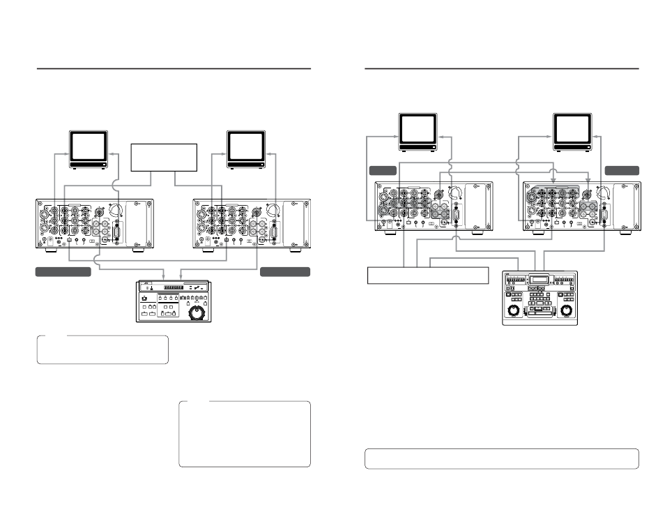
CONNECTION
– Connecting to editing sytem –
BR-DV6000 is equipped with 2 remote terminals, for the JVC bus and RS-422A for editing pur-
poses.
Ⅵ When a JVC bus-compatible editing remote controller is used:
For the editing remote controller, use RM-G800 or RM-G805.
Example: BR-DV6000 as player and recorder for cut editing of digital signals.
Note
Before connecting the cables for remote ter-
minals, ensure that the power to the VCR is
turned off.
Ⅵ Remote extension cable
To extend the cables for the remote terminals,
use the extension cable VC-G8030U (3m) (sold
separately).
Ⅵ DV cable
Use VC-VDV204 (2 m, 4P-4P) or VC-VDV206
(2 m, 4P-6P) (sold separately).
Ⅵ Related VCRs
● VHS/S-VHS VCR
No input/output of DV signals is possible.
BR-S800 + (SA-N50)
BR-S500 (player) + (SA-N50)
● DV VCR
BR-DV600/A
Monitor
Monitor
Synchronized
signal generator
DV cable (video/audio)
Remote cable
Remote cable
Player
Recorder
Note
● If RM-G800 is to be used, check whether the (x)
mark is printed on the label at the bottom of the
unit.
If there is no (x) mark, modification is required.
Consult your JVC service agent.
● For the use of RM-G800/G805, there are cer-
tain regulations regarding Electro-Magnetic
Compatibility (EMC). Consult your JVC service
agent.
/G805
33
VIDEO
LINE
IN
OUT
MONITOR
OUT
DC12V
DV
IN/OUT
IN
OUT
OFF
AUDIO
REMOTE2
IN
B-Y
R-Y
SYNC IN
TIME CODE
IN
OUT
Y
COMPONENT
OUT
CH 1/3
CH 2/4
IN
OUT
MONITOR
OUT
REMOTE1
TIMER
REC
PLAY
SERIAL
REMOTE
SINGLE
GND
Y/C
VIDEO
LINE
IN
OUT
MONITOR
OUT
DC12V
DV
IN/OUT
IN
OUT
OFF
AUDIO
REMOTE2
IN
B-Y
R-Y
SYNC IN
TIME CODE
IN
OUT
Y
COMPONENT
OUT
CH 1/3
CH 2/4
IN
OUT
MONITOR
OUT
REMOTE1
TIMER
REC
PLAY
SERIAL
REMOTE
SINGLE
GND
Y/C
L A P
I N
O U T
S E R V O
L A P
I N
O U T
S E R V O
LAP
RESET
LAP
RESET
TOTAL
RECORDER
EJECT
PLAYER
EJECT
P
AUX
CONTINUE
START
END
V.SPEED
EVENT
RENUMBER
RIPPLE
MAN.TAKE
LEARN
MENU
REC
REW
FF
STOP
STB OFF
SEARCH
PAUSE
/STILL
PLAY
REC
REW
FF
STOP
STB OFF
SEARCH
PAUSE
/STILL
PLAY
ASSEM
VIDEO
AUD-1
AUD-2
SPLIT
TC
SPLIT
CANCEL
LAST
ED
REC
EE
OUT
IN
OUT
IN
ENTRY
PREVIEW
AUTO EDIT
GOTO
REVIEW
SHIFT
ALL STOP
MAX
MIN
MONITOR
MAX
MIN
MONITOR
FWD
REV
STILL
X-1
X1
FWD
REV
STILL
X-1
X1
R E C O R D E R
P L A Y E R
HOUR
MIN
SEC
FRAME
HOUR
MIN
SEC
FRAME
P
R
VITC
LTC
CTL
VITC
LTC
CTL
BUMP
PREROLL
7
5
3
ON
OFF
EVENT No.
V.SPEED
A.SPLIT
DURATION
IN
OUT
IN
OUT
E D I T I N G C O N T R O L U N I T
R M — G 8 2 0
+
–
AUDIO
MONITOR
VIDEO
MONITOR
VIDEO
MONITOR
AUDIO
MONITOR
AUDIO IN
VIDEO OUT
SYNC IN
SYNC IN
RM-G820
SYNC IN
B.B.
B.B.
B.B.
REMOTE 1 (9-PIN)
REMOTE 1 (9-PIN)
VIDEO IN
AUDIO OUT
Ⅵ When an RS-422A-compatible remote controller is used:
For the editing remote controller, use RM-G820.
Example: use BR-DV6000 as player and recorder for cut editing of analog signals.
Ⅵ To fasten the connector of the remote
cable to the REMOTE 1 terminal, use a
screw of the inch, not metric, system.
Ⅵ In order to enhance the level of editing
precision, input synchronization sig-
nals (black burst signals) to all devices.
(
☞
Page 29)
When BR-DV3000 is to be used as the player,
input as synchronization signals the composite
signals or the Y signals of the YC signals of BR-
DV3000 to the SYNC IN terminal of BR-DV6000.
Ⅵ Related VCRs
● VHS/S-VHS VCR
BR-S800 (equipped with SA-K26, SA-R50,
SA-N50)
BR-S822 (equipped with SA-T22)
* No input/output of DV signals is possible.
● D-9 (digital S) VCR
BR-D80, BR-D85, BR-D750
(Only analog signals)
● DV VCR
BR-DV3000 (player only)
BR-DV600/A (player only)
For information on settings and other points on the operation of BR-DV6000 with
an editing system, refer to pages 64 – 68.
Synchronized signal generator
Player
Recorder
Remote cable
Monitor
Monitor
Video signals
Audio signals