JVC BR-DV6000U User Manual
Page 18
E
U
29
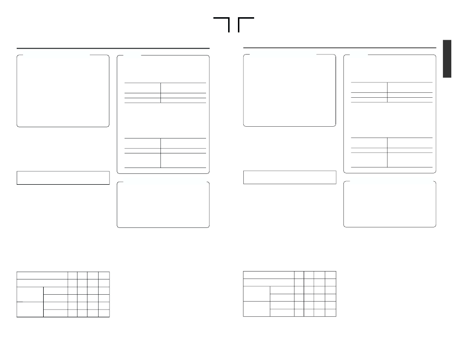
Caution on video signals
● If search images or video signals with a high
level of jitter are input, images or sound may
be distorted temporarily. Thus, input stable
signals, e.g., those having gone through a
TBC.
● A digital VCR requires that video signals for
recording be delivered from a stable source.
Video signals from an analog VCR must be
run through a TBS or TBC.
● When a component output is executed for
composite-input video, discoloration may oc-
cur on the left side of the screen. It is not a
defect.
Ⅵ Synchronization signal
In order to enhance the level of edit precision,
input synchronization signals to all the devices
of the editing system during editing.
For BR-DV6000, input external synchronization
signals into the SYNC IN terminal. For external
synchronization signals, use video signals of 1V
(p-p) or lower (e.g., black burst signals).
Types of synchronization signal:
BR-DV6000 is operated based on one of the
following 3 types of synchronization signal.
• Synchronization signals produced by the syn-
chronization signal generator inside the VCR
(INT)
• Video signals from the video signal input ter-
minal (VIDEO)
• Synchronization signals from the SYNC IN
terminal (EXT)
Selection of synchronization signals:
Synchronization signals should be selected de-
pending on whether external synchronization
input (SYNC IN) or video input (VIDEO IN) ex-
ists or on the SYNC SELECT Menu settings.
Synchronization signals are selected as shown
in the following table.
Playback
Playback
Record
Record
No
Yes
Yes
No
No
Yes
No
Yes
Memo
● During DV signal recording, the status of
synchronization signals will be as shown be-
low regardless of the SYNC SELCT menu
settings.
● During PAL signal recording from the DV ter-
minal and during playback of a tape with PAL
signals recorded, the status of synchroniza-
tion signals varies according to the SYNC
SELECT Menu settings.
Caution on synchronization signals
● For external synchronization signals, output-
signal phase adjustments cannot be per-
formed. In addition, the sub carrier cannot be
locked.
● Plugging and unplugging of external synchro-
nization signals or video input signals during
playback causes distortion of images and
sound for about 5 seconds.
SYNC IN
INT
INT
INT
INT
EXT
INT
EXT
INT
INT
VIDEO
VIDEO
VIDEO
EXT
VIDEO
EXT
VIDEO
VIDEO IN
EXTERNAL
❈
AUTO
❈
SYNC IN terminal
signal
Input
No input
Synchronization
signals
EXT
INT
SYNC SELECT
AUTO
EXTERNAL
Synchronization
signals
INT
EXT (when signals are
input to the SYNC IN
terminal)
To edit DV signals, synchronization signal in-
put is required.
❈
The above can be selected with SYNC SE-
LECT in the SYSTEM Menu screen.
E-29
Caution on video signals
● If search images or video signals with a high
level of jitter are input, images or sound may
be distorted temporarily. Thus, input stable
signals, e.g., those having gone through a
TBC.
● A digital VCR requires that video signals for
recording be delivered from a stable source.
Video signals from an analog VCR must be
run through a TBS or TBC.
● When a component output is executed for
composite-input video, discoloration may oc-
cur on the left side of the screen. It is not a
defect.
Ⅵ Synchronization signal
In order to enhance the level of edit precision,
input synchronization signals to all the devices
of the editing system during editing.
For BR-DV6000, input external synchronization
signals into the SYNC IN terminal. For external
synchronization signals, use video signals of 1V
(p-p) or lower (e.g., black burst signals).
Types of synchronization signal:
BR-DV6000 is operated based on one of the
following 3 types of synchronization signal.
• Synchronization signals produced by the syn-
chronization signal generator inside the VCR
(INT)
• Video signals from the video signal input ter-
minal (VIDEO)
• Synchronization signals from the SYNC IN
terminal (EXT)
Selection of synchronization signals:
Synchronization signals should be selected de-
pending on whether external synchronization
input (SYNC IN) or video input (VIDEO IN) ex-
ists or on the SYNC SELECT Menu settings.
Synchronization signals are selected as shown
in the following table.
Playback
Playback
Record
Record
No
Yes
Yes
No
No
Yes
No
Yes
Memo
● During DV signal recording, the status of
synchronization signals will be as shown be-
low regardless of the SYNC SELECT menu
settings.
● During NTSC signal recording from the DV
terminal and during playback of a tape with
NTSC signals recorded, the status of
synchronization signals varies according to
the SYNC SELECT Menu settings.
Caution on synchronization signals
● For external synchronization signals, output-
signal phase adjustments cannot be per-
formed. In addition, the sub carrier cannot be
locked.
● Plugging and unplugging of external synchro-
nization signals or video input signals during
playback causes distortion of images and
sound for about 5 seconds.
SYNC IN
INT
INT
INT
INT
EXT
INT
EXT
INT
INT
VIDEO
VIDEO
VIDEO
EXT
VIDEO
EXT
VIDEO
VIDEO IN
EXTERNAL
❈
AUTO
❈
SYNC IN terminal
signal
Input
No input
Synchronization
signals
EXT
DV
SYNC SELECT
AUTO
EXTERNAL
Synchronization
signals
INT
EXT (when signals are
input to the SYNC IN
terminal)
To edit DV signals, synchronization signal in-
put is required.
❈
The above can be selected with SYNC SE-
LECT in the SYSTEM Menu screen.